Wireless communication system and nodes

a wireless communication and wireless communication technology, applied in the field of multi-hop wireless communication system, can solve the problems of increasing the amount of network traffic used for relaying rreq commands, no ready way to detect, and no data communication throughput of the network suffers correspondingly

Active Publication Date: 2011-09-29
OKI ELECTRIC IND CO LTD
View PDF2 Cites 23 Cited by
  • Summary
  • Abstract
  • Description
  • Claims
  • Application Information

AI Technical Summary

Benefits of technology

[0016]An object of the present invention is to establish routes in a wireless communication network autonomously without requiring multiple nodes to flood the network with routing control information.
[0018]Yet another object is to avoid unnecessary concentration of routing traffic on a node on which the newly selected routes converge.
[0023]This routing scheme avoids the need for each of the second nodes to flood the entire network with routing control information such as RREQ packets.
[0026]When a third node selects a second node and parent node, it may also transmit routing information such as a route record packet to the first node to enable the first node to learn the route to the third node. After changing its second node selection in response to notification that the second node has failed, the third node may temporarily delay the transmission of such routing information if the third node is selected as the parent node of another third node, and transmit the routing information immediately if it is not selected as the parent node of any other node. Nodes farther from the failed second node preferably delay the transmission of the routing information for longer times, and ultimately cancel the transmission if they have already relayed routing information received from another third node. This scheme avoids the redundant transmission of routing information and can thereby avoid a needless concentration of routing traffic on a second node that is newly selected by several third nodes.

Problems solved by technology

As network size increases, however, the concentration of all network traffic onto a single sink node leads to problems.
As a result, the amount of network traffic used for relaying RREQ commands increases, and the data communication throughput of the network suffers correspondingly.
With conventional many-to-one routing, however, in which once a node has selected a low cost path it continues to select that path until it receives a RREQ command with a lower path cost, a node that has a multi-hop connection to the failed sink node has no ready way to detect that the sink node to which it is connected has failed.
A further problem is that to switch its connection from a first sink node that has failed to a second sink node that is working, a node must inform the second sink node of the switchover.
This can be done by transmitting a RREC command to the second sink node, but if all the nodes that switch their connections from the first sink node to the second sink node send RREC commands at the same time, the resulting concentration of traffic on the second sink node leads to collisions and other problems, and the second sink node may be unable to obtain accurate information about the nodes to which it is now connected.

Method used


Image

  • Wireless communication system and nodes
  • Wireless communication system and nodes
  • Wireless communication system and nodes

Examples


first embodiment

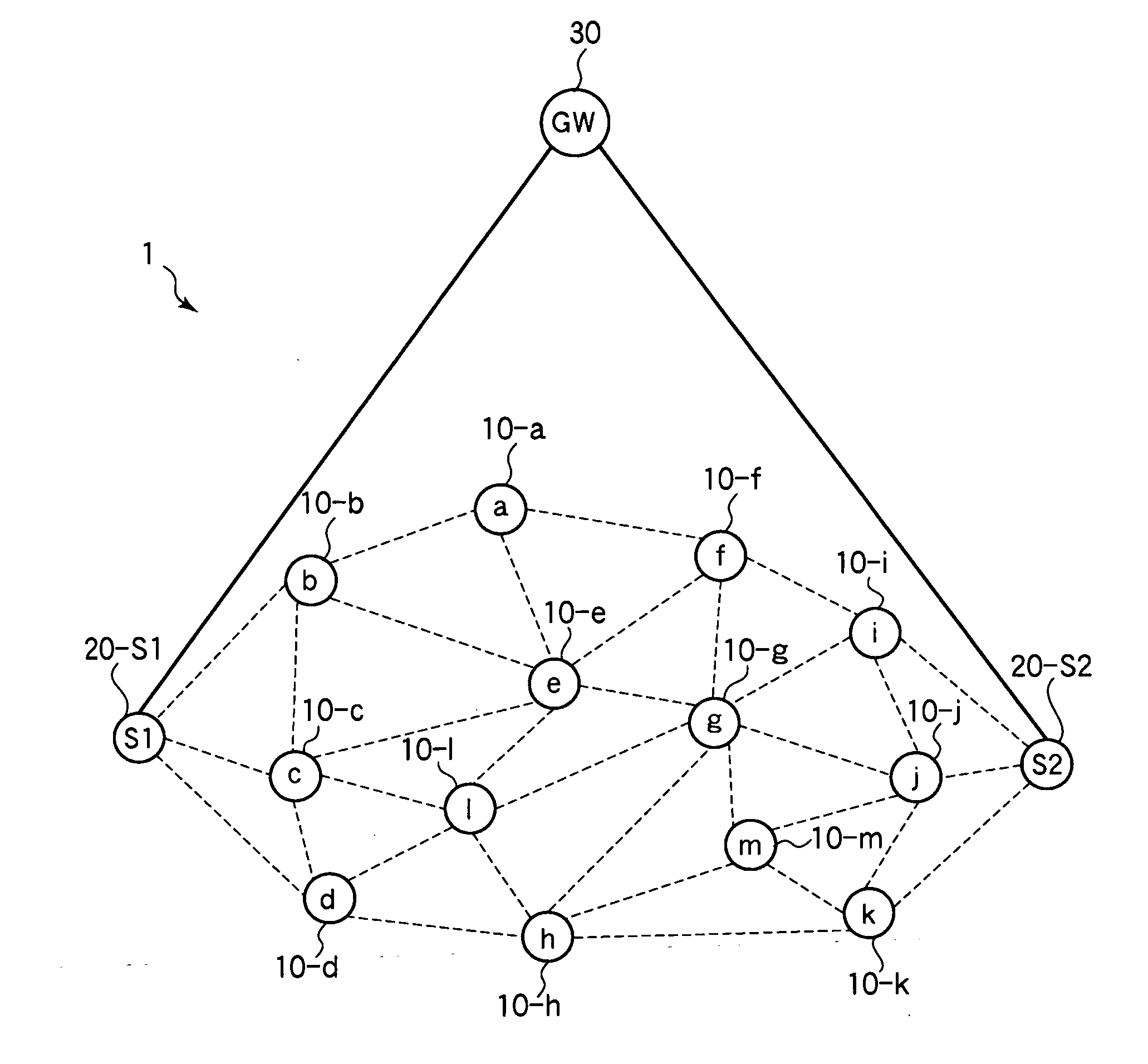
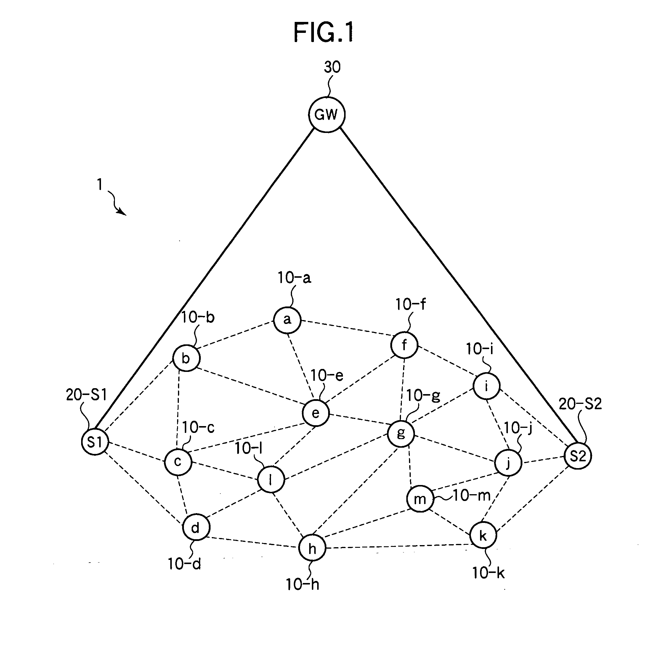
[0042]Referring to FIG. 1, the first embodiment is a wireless communication system 1 including wireless nodes 10-a to 10-m, a pair of sink nodes 20-S1 and 20-S2, and a gateway (GW) 30. For brevity, reference numeral 10 will be used when it is not necessary to identify the wireless nodes individually, and reference numeral 20 when it is not necessary to identify the sink nodes individually.

[0043]The gateway 30 is connected by a wireline network to the two sink nodes 20. In the following description, each sink node 20 has a direct wireline link to the gateway 30, as shown. In general, the wireline network may include intermediate nodes (not shown) between the gateway 30 and sink node 20. The sink nodes 20 function as relay nodes through which the wireless nodes 10 are connected to the gateway 30.

[0044]The wireless nodes 10 form a multi-hop sensor network. Each wireless node 10 acquires data from a sensor (not shown), and sends the data through one of the sink nodes 20 to the gateway 3...

second embodiment

[0088]Referring to FIG. 9, the wireless communication system 1A in the second embodiment includes a gateway 30A and five sink nodes 20-S1, 20-S2, 20-S3, 20-S4, 20-S5. A plurality of wireless nodes 10A are connected to each sink node 20.

[0089]Referring to FIG. 10, the gateway 30A includes a wireline transceiver 301, a packet receiver 302, a downstream path table 303, and a packet transmitter 304, which operate substantially as described in the first embodiment, and a newly added failure detector 305 and failure notifier 306.

[0090]The failure detector 305 detects failures of the sink nodes 20. When a failure is detected, the failure notifier 306 generates a control packet referred to below as a failure notification packet and sends it via the packet transmitter 304 and active sink nodes 20 to the wireless nodes 10A.

[0091]Next the operation of the second embodiment will be described, starting from the state depicted in FIG. 9.

[0092]At regular intervals, the failure detector 305 in the ...

third embodiment

[0105]The third embodiment is similar to the second embodiment but employs modified wireless nodes.

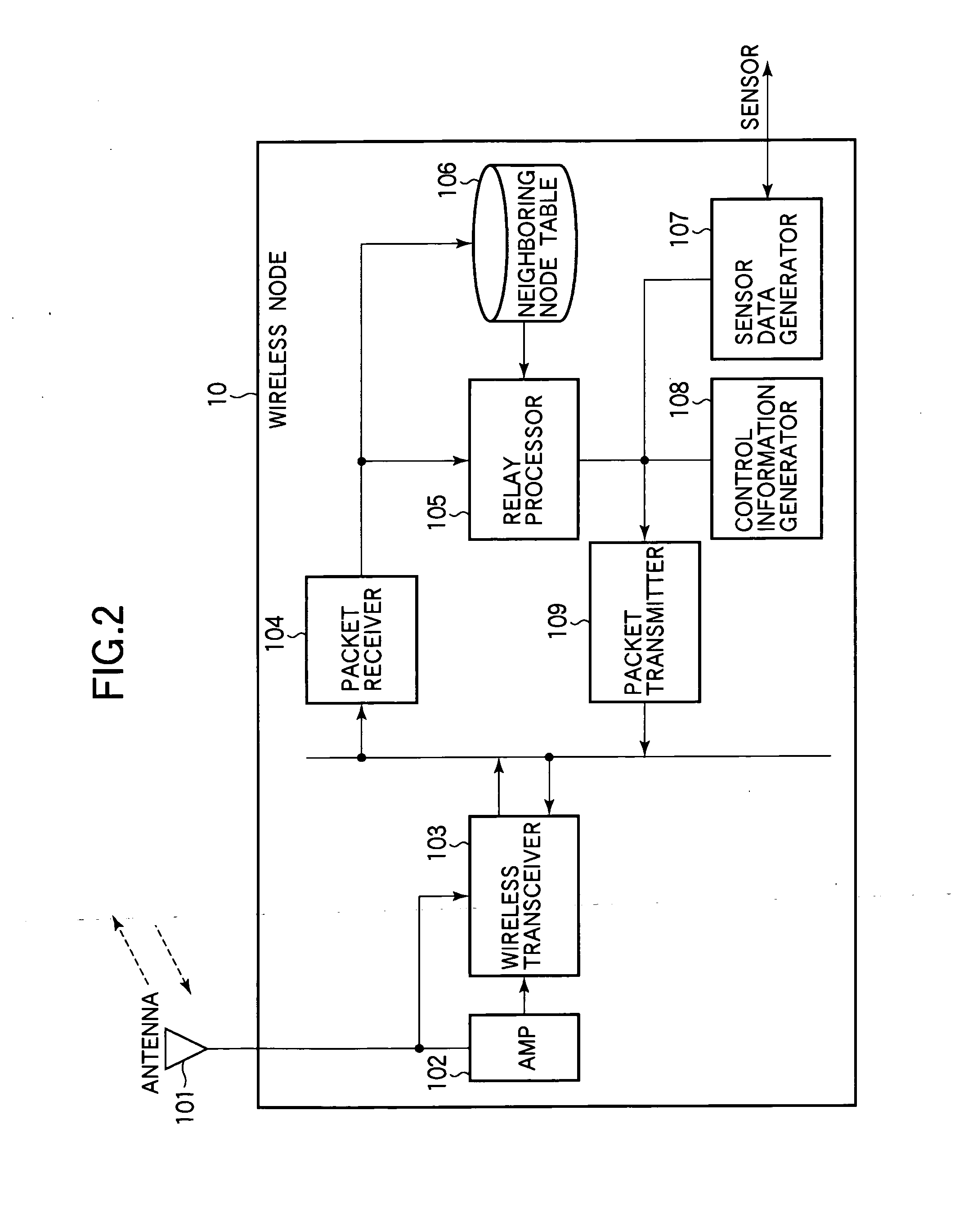
[0106]Referring to FIG. 15, each of the wireless nodes 10B in the third embodiment is generally similar to the wireless nodes in the preceding embodiments but includes an additional control information buffer 111 disposed between the control information generator 108 and the packet transmitter 109. When the control information generator 108 generates a packet such as an RREC packet to be sent to the gateway 30A or to a sink node 20 to establish a downstream path, the control information buffer 111 may store the packet for a prescribed time before passing the packet to the packet transmitter 109. The prescribed time may be fixed or variable.

[0107]The third embodiment operates in the same way as the second embodiment except for the transmission of Hello packets following a change of route to the gateway 30A. The following description will therefore focus on the process following the tran...


PUM


Abstract

A wireless communication system includes a first node, multiple second nodes, and multiple third nodes that communicate with the first node through the second nodes. The second and third nodes transmit control information to their neighboring third nodes, which calculate link costs from the reception status of the control information. The control information transmitted by each node includes a path cost indicating the cost of a path between the transmitting node and the first node. From the path costs in received control information, each third node selects a second node through which to communicate with the first node, and selects a parent node as the destination of the first hop on the path through the selected second node to the first node. Routing is thereby accomplished autonomously without having the second nodes flood the system with routing requests.

Description

BACKGROUND OF THE INVENTION[0001]1. Field of the Invention[0002]The present invention relates to a multi-hop wireless communication system and its nodes.[0003]2. Description of the Related Art[0004]A multi-hop wireless communication system enables wireless nodes that are not within direct radio range of each other to communicate by relay through intermediate wireless nodes. Various routing protocols are used to ensure that communications are relayed over appropriate routes. For example, in ZigBee Specification Revision 17 (ZigBee Document 053474r17), the ZigBee Alliance has standardized a many-to-one routing protocol that enables a so-called sink node to collect data efficiently from a plurality of other nodes. Applications in environmental sensing and telemetering are envisioned.[0005]The ZigBee protocol and other similar protocols are based on link costs. A link cost is quantity that indicates the quality or reliability of a direct (one-hop) wireless link between two neighboring n...

Claims


Application Information

Patent Timeline
Patent Type & Authority Applications(United States)
IPC IPC(8): H04W24/00H04W40/00
CPCH04L45/04H04W28/04H04W88/04H04W40/30H04W28/06
Inventor NOZAKI, MASANORIYANAGIHARA, KENTAROUNISHIMURA, HIROSHIKUBO, YUKI
Owner OKI ELECTRIC IND CO LTD
Why Eureka
Try Eureka