X-ray generating apparatus and inspection apparatus using the same therein

a generating apparatus and generating technology, applied in the direction of x-ray tube targets, x-ray tube targets, instruments, etc., can solve the problems of high aspect ratio, and difficult to obtain such a stripe-like x-ray (multi-line x-ray,

Active Publication Date: 2011-09-29
RIGAKU CORP
View PDF2 Cites 43 Cited by
  • Summary
  • Abstract
  • Description
  • Claims
  • Application Information

AI Technical Summary

Benefits of technology

[0011]As was mentioned above, according to the present invention, there can be provided the X-ray generating apparatus for enabling to forma very fine width stripe-like X-ray (i.e., the multi-line X-ray) having a size (e.g., line width) of μm order, and there can be also obtained a very s

Problems solved by technology

By the way, in general, for producing such stripe-like X-ray (multi-line X-ray), it can be considered to dispose a transmission-type diffraction grating in a front of the X-ray source, but in actual, there can be assumed that the stripe-like X-ray (or, multi-line X-ray) having a size of micrometer (μm) order (e.g., line width) is required, depending on the way of use thereof; however, with the conventional technology, it is difficult to obtain such the stripe-like X-ray.
This i

Method used


Image

  • X-ray generating apparatus and inspection apparatus using the same therein
  • X-ray generating apparatus and inspection apparatus using the same therein
  • X-ray generating apparatus and inspection apparatus using the same therein

Examples


embodiment 1

[0040]FIG. 6 attached herewith is a perspective view for showing an enclosure type X-ray generating apparatus having a static metal target therein, and FIG. 6 attached herewith is a partial enlarged cross-section view thereof, including that metal target therein.

[0041]Namely, in the structure of the X-ray generating apparatus according to this embodiment 1, an electron source 2 and an anode (e.g., a target) are provided within an inside of a body of an X-ray tube, which is made of stainless steel. Further, the electron source 2 is so constructed that it comprises a filament, building up so-called a cathode, being heated by current supplied from a filament current source 41, and thereby for emitting thermo electrons (e.g., the electron beam) therefrom, and an electron lens 22 for converging the electron beams emitted into a desired diameter. However, this electron lens 22 is not always necessary, according to the present invention, but it is enough that, as was mentioned above, the e...

embodiment 2

[0047]FIG. 9 attached herewith is a cross-section view for showing the entire of so-called a rotating anode X-ray tube, i.e., being an X-ray generating apparatus having a rotating target (e.g., an anticathode) therein, and FIG. 10 attached herewith is an entire perspective view for showing the details of the rotating metal target thereof.

[0048]As is shown in FIG. 9, the X-ray generating apparatus having the rotating target (the anticathode) comprises a rotating anode (e.g., the target) 3′, which is provided together with a filament 21, as being the electron source 2, within an inside of the X-ray tube body 1 made of stainless steel, being constructed to be vacuum within an inside thereof. Also, a reference numeral 36 in the figure depicts a driver portion, which comprises a means therein, for rotating / driving the rotating target, such as, an electric motor, etc., the detailed structure of which will be explained below, and to that driver portion 36 is also guided the coolant 5; alth...


PUM


Abstract

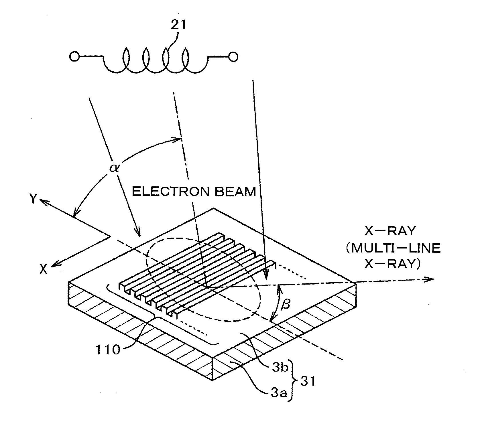
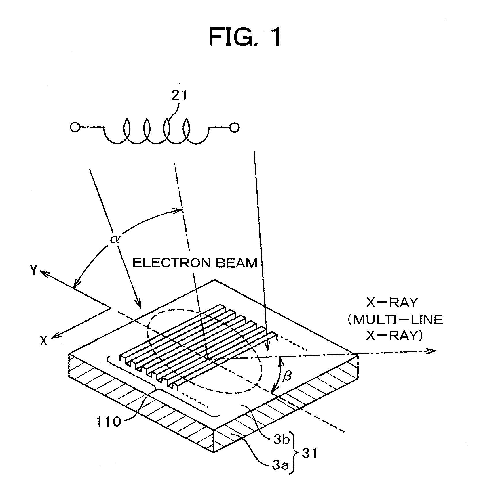
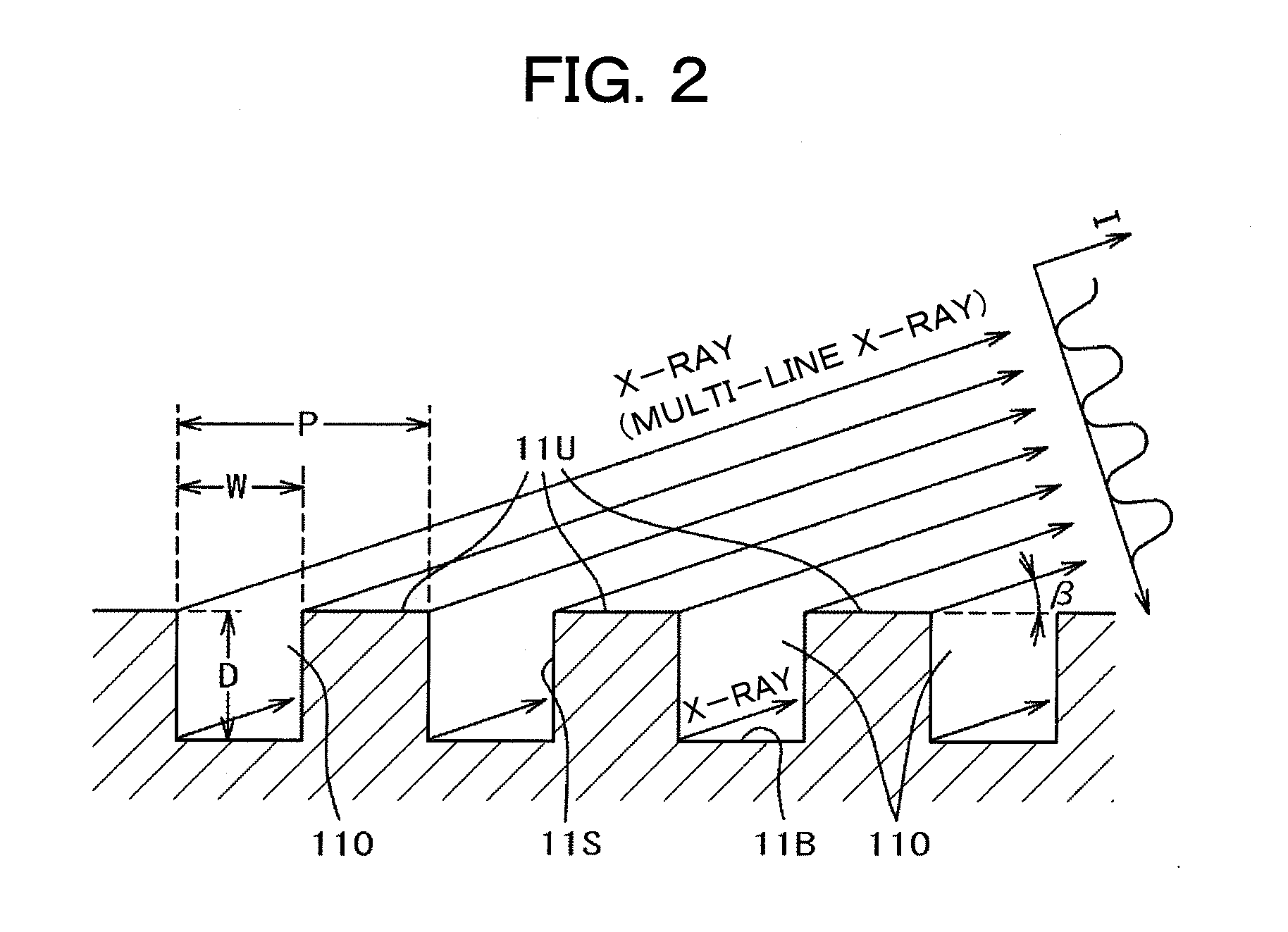
An X-ray generating apparatus is disclosed which includes a tube body having a vacuum interior, an electron source provided within the tube body to generate an electron beam, a target, within the tube body that is irradiated with the electron beam to generate an X-ray, and an X-ray window for taking out the X-ray generated outside of the tube body. A plurality of grooves are formed on a surface of a member building up the target. The grooves each have a fine width and are inclined by a predetermined angle (α), from a direction perpendicular to an elongating direction of the grooves, so that they bridge over the plural numbers of grooves. The X-ray generating apparatus is configured such that a multi-line X-ray generating from the plural numbers of multi-line targets, which are formed between the grooves, emits at a predetermined extraction angle (β), passing through the X-ray window. An inspection apparatus which includes the X-ray generating apparatus is also disclosed.

Description

TECHNICAL FIELD[0001]The present invention relates to an X-ray generating apparatus for irradiating X-ray therefrom, and in particular, it relates to an X-ray generating apparatus for enabling to emit a stripe-like X-ray (or, multi-line X-ray) therefrom, as well as, an inspection apparatus applying the same therein.[0002]Apparatuses applying the X-ray therein are used, widely, for the purposes of analysis or explication of an object (a sample), and further an inspection thereof, etc., in various technical fields. As an X-ray source in such the apparatuses is applied, though differing from depending on a way of use thereof, etc., one for irradiating stripe-like X-ray (or, multi-line X-ray) therefrom, as well as, a normal point-like X-ray source.[0003]For example, in the following Patent Document 1 is already known an X-ray source, wherein an object, upon which charged particles strike, has a means for achieving a converging / diverging effect of radiation, such as, being made of a zone...

Claims


Application Information

Patent Timeline
IPC IPC(8): H01J35/18G01N23/04
CPCH01J35/08H01J2235/086H01J2235/081H01J35/112
Inventor AOKI, SHOZONONOGUCHI, MASAHIRO
Owner RIGAKU CORP
Why Eureka
Try Eureka