Rotatable tool for chip removing machining as well as a loose top and a basic body therefor

a technology of rotating tools and loose tops, which is applied in the direction of shaping cutters, manufacturing tools, twist drills, etc., can solve the problems of extreme, not to say unattainable, and the risk of incorrect mounting of loose tops is 50%, and achieves strong and robust effects

Active Publication Date: 2011-09-29
SANDVIK INTELLECTUAL PROPERTY AB
View PDF49 Cites 31 Cited by
  • Summary
  • Abstract
  • Description
  • Claims
  • Application Information

AI Technical Summary

Benefits of technology

[0011]Yet another object of the invention is to provide a

Problems solved by technology

However, the concurrent requirements of fit not only between the center pin and the hole, but also between the drivers and the coupling part, impose extreme, not to say unattainable, requirements of manufacturing precision.
In addition, a conflicting problem will arise if good precision peradventure would be achieved, viz. that the mounting and dismounting of the loose top become difficul

Method used


Image

  • Rotatable tool for chip removing machining as well as a loose top and a basic body therefor
  • Rotatable tool for chip removing machining as well as a loose top and a basic body therefor
  • Rotatable tool for chip removing machining as well as a loose top and a basic body therefor

Examples


Embodiment Construction

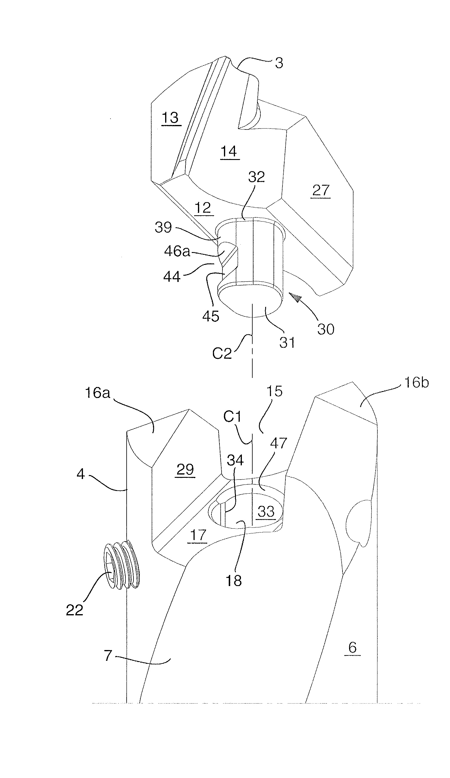
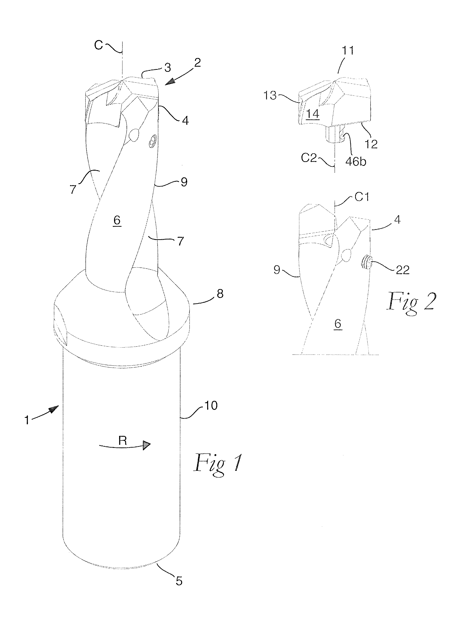
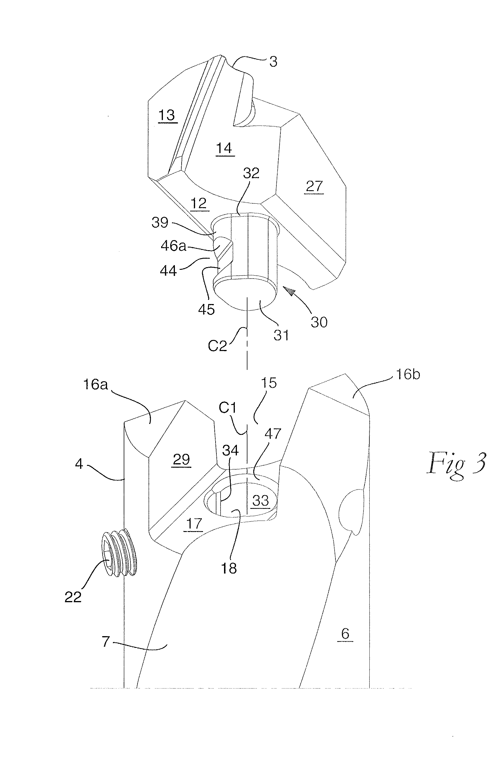
[0027]In the drawings, the loose top tool according to an embodiment of the invention is exemplified in the form of a twist drill, which includes a basic body 1 and a loose top 2, in which the requisite cutting edges 3 are included. In its assembled, operative state according to FIG. 1, the tool is rotatable around a geometrical center axis designated C, more precisely in the direction of rotation R. The basic body 1 includes front and rear ends 4, 5 between which a center axis C1 specific to the basic body extends. In the backward direction from the front end 4, a cylindrical or rotationally symmetrical envelope surface 6 extends, in which two chip flutes 7 are countersunk, which in this case are helicoidal but which also may be straight. In the example, the chip flutes 7 terminate in a collar 8, separating the front part 9 of the basic body from a rear part 10, which has a diameter that is greater than that of the part 9, and is intended to be attached to a driving machine (not sh...


PUM

PropertyMeasurementUnit
Fractionaaaaaaaaaa
Angleaaaaaaaaaa
Angleaaaaaaaaaa

Abstract

A rotatable tool for chip removing machining, including a basic body having front and rear ends between which there extends a first geometrical center axis (C1) around which the basic body is rotatable in a predetermined direction of rotation, and a loose top having front and rear ends between which a second geometrical center axis (C2) extends. The front end of the basic body includes a jaw, which is delimited by two drivers and an intermediate bottom and in which a part of the loose top is received. A centering pin protrudes axially rearward from the loose top and is inserted in an axial center hole, which mouths in the bottom of the jaw and in which a threaded hole mouths for a screw co-operating with the center pin. The center hole includes a cylindrical support surface, which is concentric with the center axis (C1) of the basic body and against which the centering pin of the loose top is pressed by the screw. The centering pin of the loose top includes first and second diametrically opposed, external surfaces, each having an axial extension and a peripheral extension, the first external surface forming a contact surface that is pressed against the support surface of the center hole and extends tangentially between two axially extending boundary generatrices, which are situated along an imaginary circumscribed circle (S2) having a center (MP2) coinciding with the center axis (C2) of the loose top, and between which an arc angle (β) is less than 180°, the second external surface forming a clearance surface that lacks contact with the inside of the center hole as a consequence of the cross-sectional area of the centering pin being smaller than the cross-sectional area of the center hole. The circumscribed circle (S2) has a radius (r2) that is equally great as the radius (r1) of an inscribed circle (S1) along the cylindrical support surface of the center hole. A greatest radial distance (RD2) between the center axis (C2) of the loose top and a point on the clearance surface of the centering pin is greater than the radius (r2) of the circumscribed circle (S2) but smaller than a corresponding distance (RD1) between the center axis (C1) of the basic body and a clearance surface situated in the center hole and opposite the support surface.

Description

[0001]This application claims priority under 35 U.S.C. §119 to Swedish Patent Application No. 1050288-8, filed on Mar. 26, 2010, which is incorporated by reference herein in its entirety.FIELD OF THE INVENTION[0002]The present invention relates generally to a rotatable tool for chip removing machining of the type that includes a basic body having front and rear ends between which there extends a first geometrical center axis around which the basic body is rotatable in a predetermined direction of rotation, and a loose top having front and rear ends between which a second geometrical center axis extends. The front end of the basic body includes a jaw, which is delimited by two drivers and an intermediate bottom and in which a part of the loose top is received. A centering pin protrudes axially rearward from the loose top and is inserted in an axial center hole, which mouths in the bottom of the jaw and in which a threaded hole mouths for a screw co-operating with the center pin.[0003...

Claims


Application Information

Patent Timeline
IPC IPC(8): B23C5/22B23B27/22
CPCB23B51/02B23B2251/02B23B2251/50Y10T408/907Y10T408/90993Y10T407/24B23B2265/12B23B27/22B23B51/00B23C5/00B23Q11/02B23C5/22B23B2240/36
Inventor PABEL, HELENAAARE, MAGNUS
Owner SANDVIK INTELLECTUAL PROPERTY AB
Why Eureka
Try Eureka