

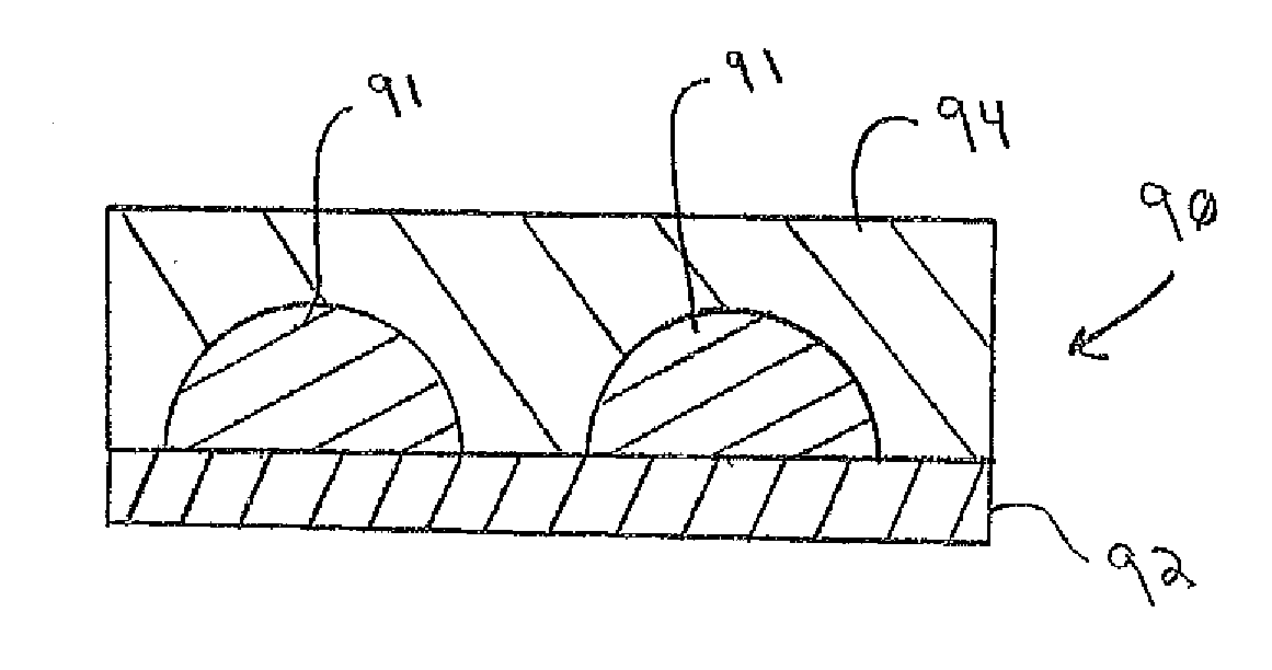
Solar control coatings with discontinuous metal layer
a technology of discontinuous metal layer and solar control coating, which is applied in the direction of coatings, transportation and packaging, chemical instruments and processes, etc., can solve the problems of glass substrate cutting, haze, and aesthetically undesirable haze, and achieve the effect of increasing the visible light absorption of the coating
- Summary
- Abstract
- Description
- Claims
- Application Information
AI Technical Summary
Benefits of technology
Problems solved by technology
Method used
Image

Examples
example 1
A coating was deposited by a conventional MSVD coater (commercially available from Applied Materials) on a 6 mm piece of clear glass. The coated glass had the following structure:
titania 40 Åzinc stannate190 Åzinc oxide (90 / 10) 80 Åtitanium 30 Åsilver150 Åzinc oxide120 Åzinc stannate450 Åzinc oxide120 ÅInconel 22 ÅS.C. silver 25 Åzinc stannate110 Åzinc oxide 70 Åtitanium 30 Åsilver180 Åzinc oxide110 Åzinc stannate200 Åclear glass 6 mm
This coated glass was heat treated as described above and had the optical characteristics shown in Table 1 below. The article was incorporated into a standard IGU as the outer ply (the inner ply was uncoated 6 mm clear glass) and had the optical characteristics set forth in Table 2 below.
example 2
A coating was deposited by a conventional Airco MSVD coater on a 6 mm piece of Starphire® glass. The coated glass had the following structure:
titania 40 Åzinc stannate170 Åzinc oxide (90 / 10) 80 Åtitanium 20 Åsilver150 Åzinc oxide120 Åzinc stannate480 Åzinc oxide120 ÅInconel 22 ÅS.C. sliver 25 Åzinc stannate110 Åzinc oxide 70 Åtitanium 20 Åsilver180 Åzinc oxide110 Åzinc stannate220 ÅStarphire ® glass 6 mm
This coated glass was heat treated as described above and had the optical characteristics shown in Table 1 below. The article was incorporated into a standard IGU as the outer ply (the inner ply was uncoated 6 mm Starphire® glass) and had the optical characteristics set forth in Table 2 below.
example 3
A coating was deposited by a conventional Airco MSVD coater on a 6 mm piece of Optiblue® glass. The coated glass had the following structure:
titania 40 Åzinc stannate170 Åzinc oxide (90 / 10) 80 Åtitanium 20 Åsilver150 Åzinc oxide120 Åzinc stannate480 Åzinc oxide120 ÅInconel 22 ÅS.C. silver 25 Åzinc stannate110 Åzinc oxide 70 Åtitanium 20 Åsilver180 Åzinc oxide110 Åzinc stannate220 ÅOptiblue ® glass 6 mm
This coated glass was heat treated as described above and had the optical characteristics shown in Table 1 below. The article was incorporated into a standard IGU as the outer ply (the inner ply was uncoated 6 mm Starphire® glass) and had the optical characteristics set forth in Table 2 below.
PUM
| Property | Measurement | Unit |
|---|---|---|
| visible light transmittance | aaaaa | aaaaa |
| wavelength | aaaaa | aaaaa |
| wavelength | aaaaa | aaaaa |
Abstract
Description
Claims
Application Information