Vehicle control device and vehicle drive system

Inactive Publication Date: 2011-09-29
AISIN AW CO LTD
View PDF10 Cites 18 Cited by
  • Summary
  • Abstract
  • Description
  • Claims
  • Application Information

AI Technical Summary

Benefits of technology

[0049]As has been described above, with the vehicle control device according to the present invention, because the engine drag (engine brake, or co-rotation of the engine) in the running idle state is avoided, the energy loss associated with the engine drag can be suppressed. In that case, in the vehicle drive system in which the output shaft of the rotary electric machine is drivingly connected to either one of the front and rear wheels of the vehicle as characterized in the above-described struc

Problems solved by technology

Consequently, there has been a problem that the response in the driving force transmission becomes worse by a degree corresponding to the period of time required to start the engine as described above.
For this reason, there has been a problem that the response in the driving force transmission becomes worse by a degree corresponding to the period of time required to complete the engagement of the advanci

Method used


Image

  • Vehicle control device and vehicle drive system
  • Vehicle control device and vehicle drive system
  • Vehicle control device and vehicle drive system

Examples


Example

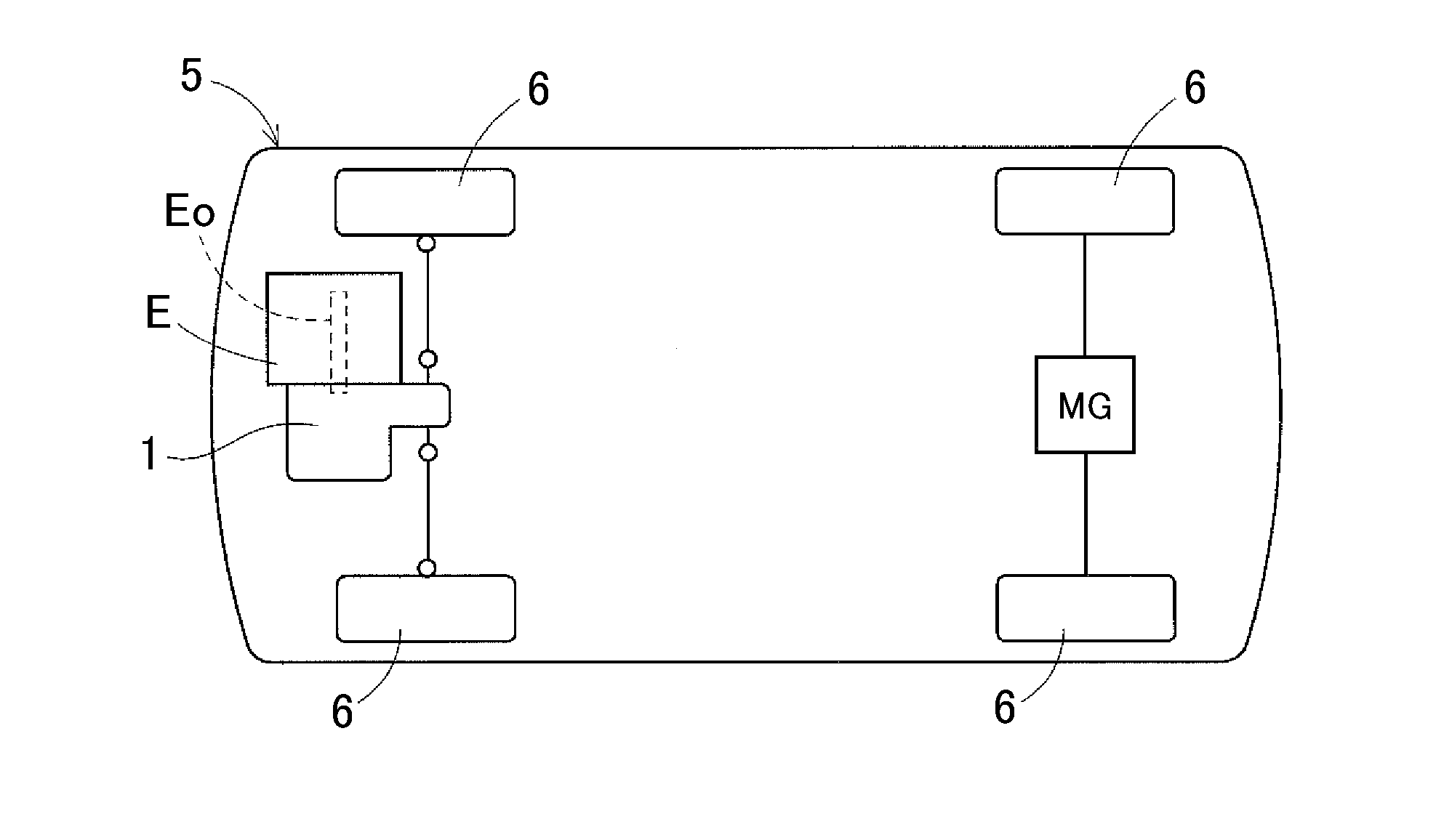
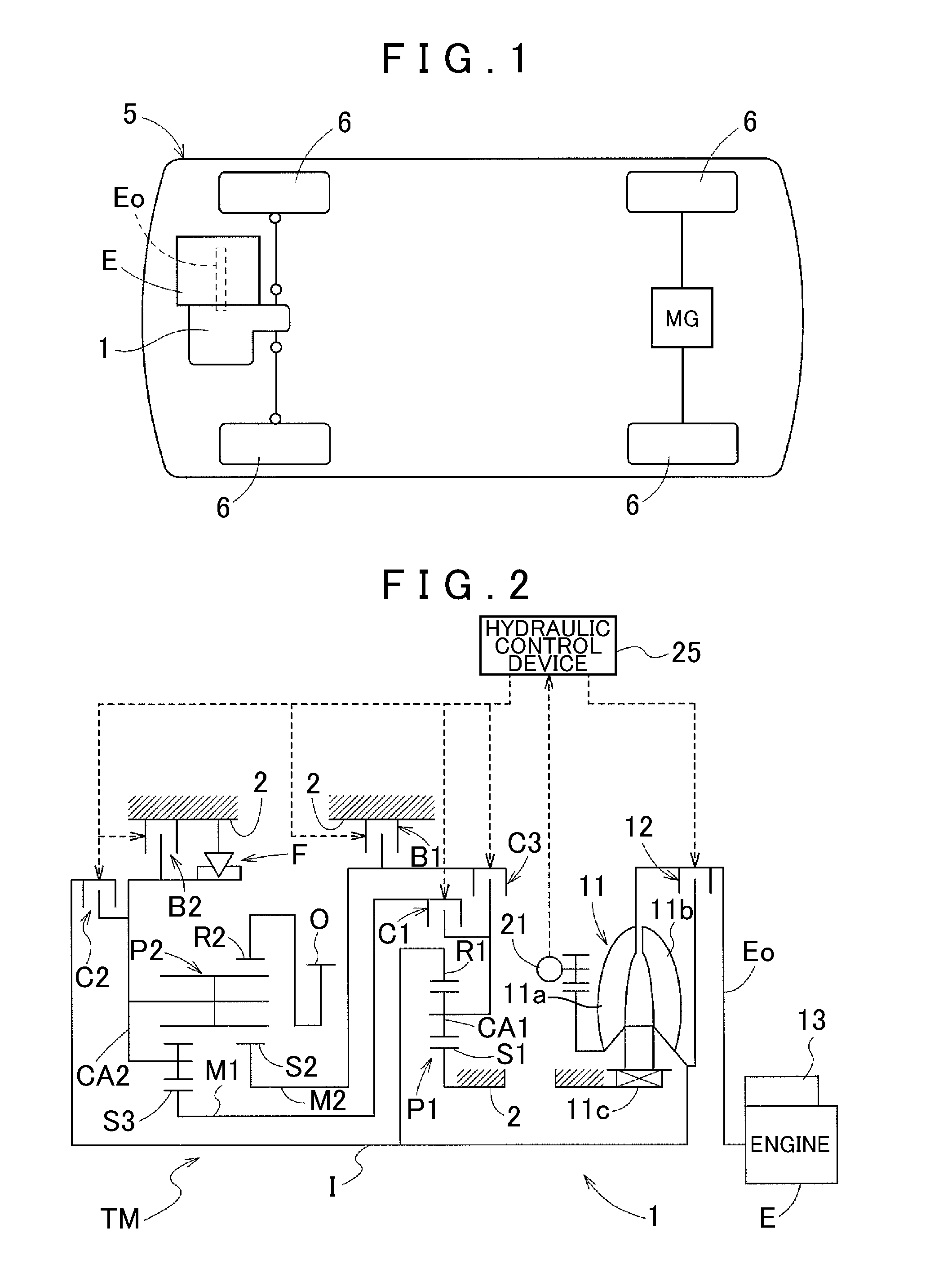
[0067]A first embodiment of a vehicle control device according to the present invention will be described with reference to the accompanying drawings. In the present embodiment, the vehicle control device according to the present invention will be described as an example applied to a drive unit for a hybrid vehicle. FIG. 1 is a diagram showing an overall structure of a vehicle 5 equipped with a vehicle drive unit 1 according to the present embodiment. As shown in this diagram, the vehicle drive unit 1 according to the present embodiment is arranged adjacent in the direction of width of the vehicle 5 to an engine E that is transversely mounted in the vehicle 5. In addition, an output gear O provided in the vehicle drive unit 1 is drivingly connected to front wheels of the vehicle 5 via a counter gear mechanism, a differential device, and so forth that are not shown. In the present embodiment, the vehicle 5 is also equipped with a rotary electric machine MG that can output a driving f...

Example

[0159]A second embodiment of the present invention will be described with reference to the accompanying drawings. FIG. 14 is a schematic diagram showing a structure of a drive transmission system of a vehicle drive unit 1 according to the present embodiment. Note that FIG. 14 shows the structure omitting some of axially symmetric parts, in the same manner as in FIG. 2. Here, the structure is also shown omitting the hydraulic control system because the hydraulic control system has the same structure as in the first embodiment. The structure of the vehicle drive unit 1 is the same as that obtained by removing the first brake B1 from the vehicle drive unit 1 in the first embodiment. In the vehicle drive unit 1 of the present embodiment, due to the lack of the first brake B1, the number of the shift speeds provided in the transmission device TM is smaller than that in the first embodiment. Accordingly, there are partial differences from the first embodiment in the contents of the contro...


PUM


Abstract

A control device for controlling a vehicle drive unit including an input member drivingly connected to an engine; an output member drivingly connected to a wheel; and a transmission device that includes engagement elements, that switches between shift speeds by control of engagement and disengagement of engagement elements, and that transmits a rotational driving force of the input member to the output member at a speed changed at a speed ratio of each of the shift speeds. The control device includes a control unit that controls the transmission device to achieve a one-way transmission speed in a running idle state in which a vehicle is running while the rotational driving force of the input member is not transmitted to the output member and a rotational speed of the engine is controlled to a predetermined idle speed. The transmission device has, as one of the shift speeds, the one-way transmission speed at which the rotational driving force from the input member to the output member is transmitted but the rotational driving force from the output member to the input member is not transmitted.

Description

INCORPORATION BY REFERENCE[0001]The disclosure of Japanese Patent Application No. 2010-070436 filed on Mar. 25, 2010, including the specification, drawings and abstract is incorporated herein by reference in its entirety.BACKGROUND OF THE INVENTION[0002]The present invention relates to a control device for controlling a vehicle drive unit equipped with an input member drivingly connected to an engine, an output member drivingly connected to wheels, and a transmission device that transmits a rotational driving force of the input member to the output member at a speed changed at a speed ratio of each shift speed, and to a vehicle drive system equipped with the vehicle drive unit controlled by such a control device.DESCRIPTION OF THE RELATED ART[0003]As a conventional vehicle drive unit, for example, a device described in Japanese Patent Application Publication No. JP-A-7-266932 has already been known. In this drive unit, when a running vehicle is placed in a predetermined mild deceler...

Claims


Application Information

Patent Timeline
IPC IPC(8): B60W10/10B60W30/18B60W10/08B60W10/02F16H61/00F16H63/50
CPCB60K6/52B60W30/18072B60W2030/1809B60Y2300/18083Y10T74/20018F16H61/061F16H2061/044Y02T10/6265F16H61/0213Y02T10/62
Inventor SUZUKI, TAKEHIKOKOMIZO, KYOSUKESEKII, TAKAHIRO
Owner AISIN AW CO LTD
Why Eureka
Try Eureka