Transmission for hybrid vehicle

a hybrid vehicle and transmission technology, applied in the direction of battery/cell propulsion, transportation and packaging, etc., can solve the problems of complicated control, deterioration of regenerative efficiency at deceleration, and increase in size and weight of the transmission, so as to reduce the size of the motor, increase the torque of the motor, and make light and compact.

Inactive Publication Date: 2011-10-06
HONDA MOTOR CO LTD
View PDF19 Cites 23 Cited by
  • Summary
  • Abstract
  • Description
  • Claims
  • Application Information

AI Technical Summary

Benefits of technology

[0011]With this arrangement, the power of the motor can be output from an output shaft through the intermediary of gear shift stages of the second speed changing unit, so that the output of the motor can be controlled to a relatively low level while obtaining sufficient power, thus making it possible to reduce the size of the motor. Further, connecting the first speed changing unit and the second speed changing unit by the connecting unit allows the second speed changing unit to be used from the internal combustion engine side, so that the construction of the first speed changing unit can be simplified and the transmission can be therefore made lightweight and compact.
[0012]At this time, any one gear shift stage established by the second speed changing unit is preferably lower than any one gear shift stage established by the first speed changing unit. This makes it possible to increase the torque of the motor during a low-speed travel and to reduce the size of the motor, thus allowing the transmission to have a compact construction.
[0013]Further, any one gear shift stage established by the second speed changing unit is preferably higher than any one gear shift stage established by the first speed changing unit. This makes it possible to control the rotational speed of the power shaft of the motor to be relatively low even when the vehicle is traveling at a high speed by the power of the motor, and a reduced maximum rotational speed of the motor allows the size of the motor to be reduced, so that the transmission can be made compact.
[0014]Further, according to the present invention, at least one of the first speed changing unit and the second speed changing unit can be constructed of a stepless speed changing mechanism, such as a CVT (Continuously variable transmission), which continuously establishes gear shift stages. The CVT may not be capable of supplying a sufficient output in an area where a high torque is generated. According to the present invention, however, connecting the first speed changing unit to which the power of the internal combustion engine is supplied and the second speed changing unit to which the power of the motor is supplied allows the outputs of both the motor and the internal combustion engine to be supplied, making it possible to compensate for a deficient output in a high-torque area. Further, the drive on the motor can be maintained during an instantaneous idle running (coasting) when an accelerator (gas) pedal is turned off, thus making it easy to maintain a speed against a load variation.
[0015]Further, in the present invention, preferably, the first speed changing unit is constructed of a rotation transmitting element provided with a plurality of gears corresponding to the gear shift stages, and the rotation transmitting element is provided with a one-way clutch that engages or disengages the transmission of the rotation between gears according to the rotational speed to be transmitted. As an embodiment for this purpose, the one-way clutch of the rotation transmitting element may be provided between the gear and a supporting shaft that supports the gear. With this arrangement, when, for example, the gear and the supporting shaft are connected by the one-way clutch at a higher gear shift stage in the process for moving into a higher gear, the supporting shaft rotates at a higher speed due to the action of the speed change, causing automatic disengagement of the connection between the gear and the supporting shaft by the one-way clutch at a lower gear shift stage. Thus, the speed changing time can be shortened.

Problems solved by technology

However, the constant engagement between the input shaft of the speed changing unit and the power shaft of the engine causes engine brake to be added, thus resulting in deteriorated regenerative efficiency at deceleration.
Therefore, if the friction engagement clutch is provided between the power shaft of the internal combustion engine and the input shaft, then the size and the weight of the transmission will be inevitably increased.
In addition, it would be necessary to carry out control for actuating the friction engagement clutch according to a selected shift gear or the traveling state of the vehicle, inconveniently leading to complicated control.

Method used


Image

  • Transmission for hybrid vehicle
  • Transmission for hybrid vehicle
  • Transmission for hybrid vehicle

Examples


first embodiment

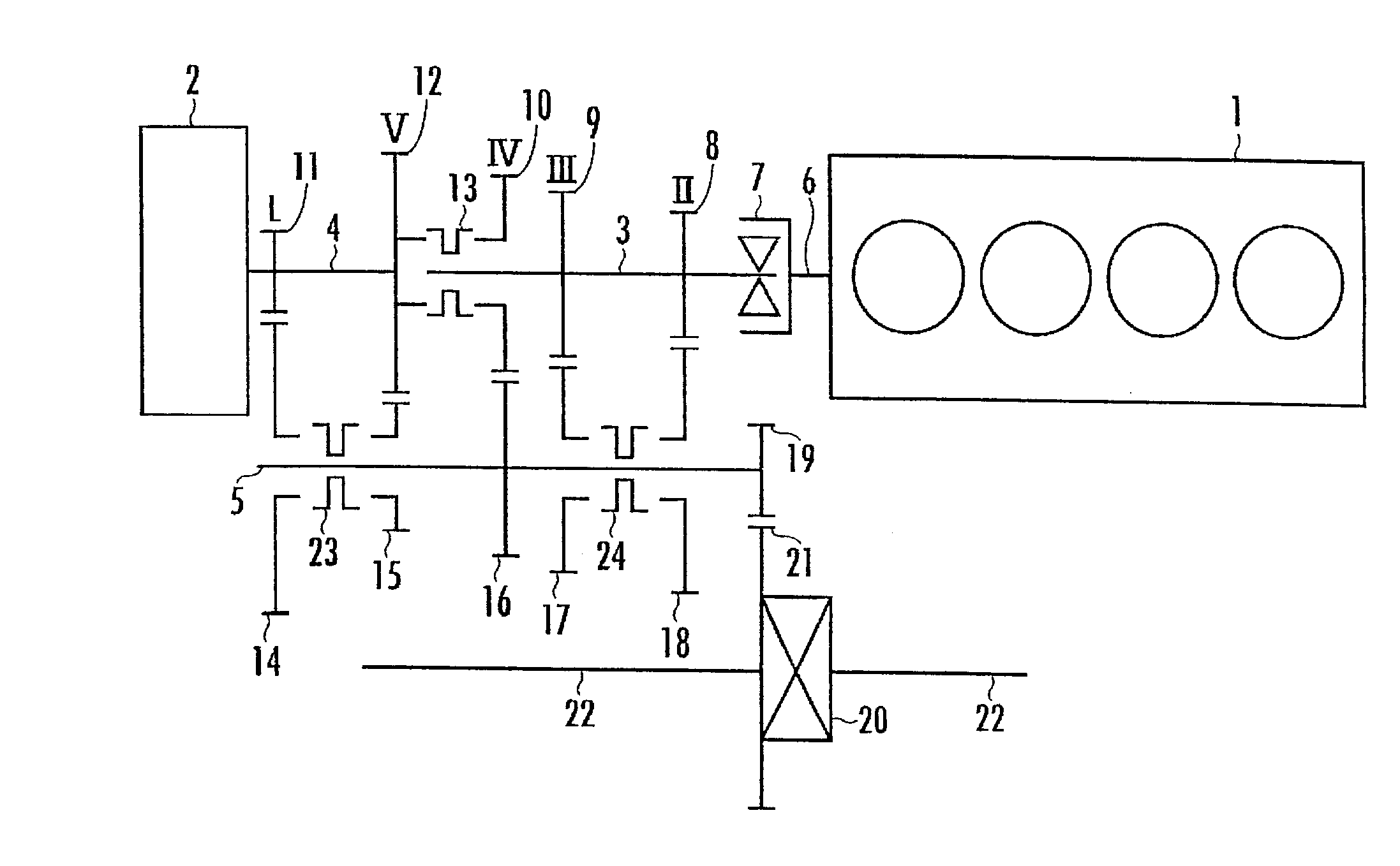
[0016]FIG. 1 schematically illustrates a transmission for a hybrid vehicle in the present invention. As illustrated in FIG. 1, a transmission according to the present embodiment is provided with an engine 1 (internal combustion engine) and a motor 2 (motor / generator) as the driving sources. The transmission is further provided with a first input shaft 3, a second input shaft 4 and an output shaft 5, which are all rotatively mounted. The first input shaft 3 and the second input shaft 4 are disposed coaxially with each other, while the output shaft 5 is disposed in parallel to the first input shaft 3 and the second input shaft 4.

[0017]The first input shaft 3 is extendedly provided, being disposed coaxially with an engine power shaft 6 through which the power rotation from the engine 1 is output, and a one-way clutch 7 is provided between the first input shaft 3 and the engine power shaft 6. The engine power shaft 6 and the first input shaft 3 are automatically engaged / disengaged by th...

fourth embodiment

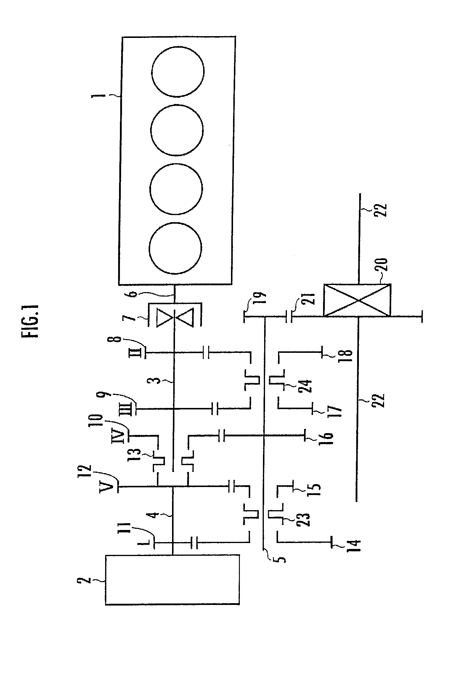
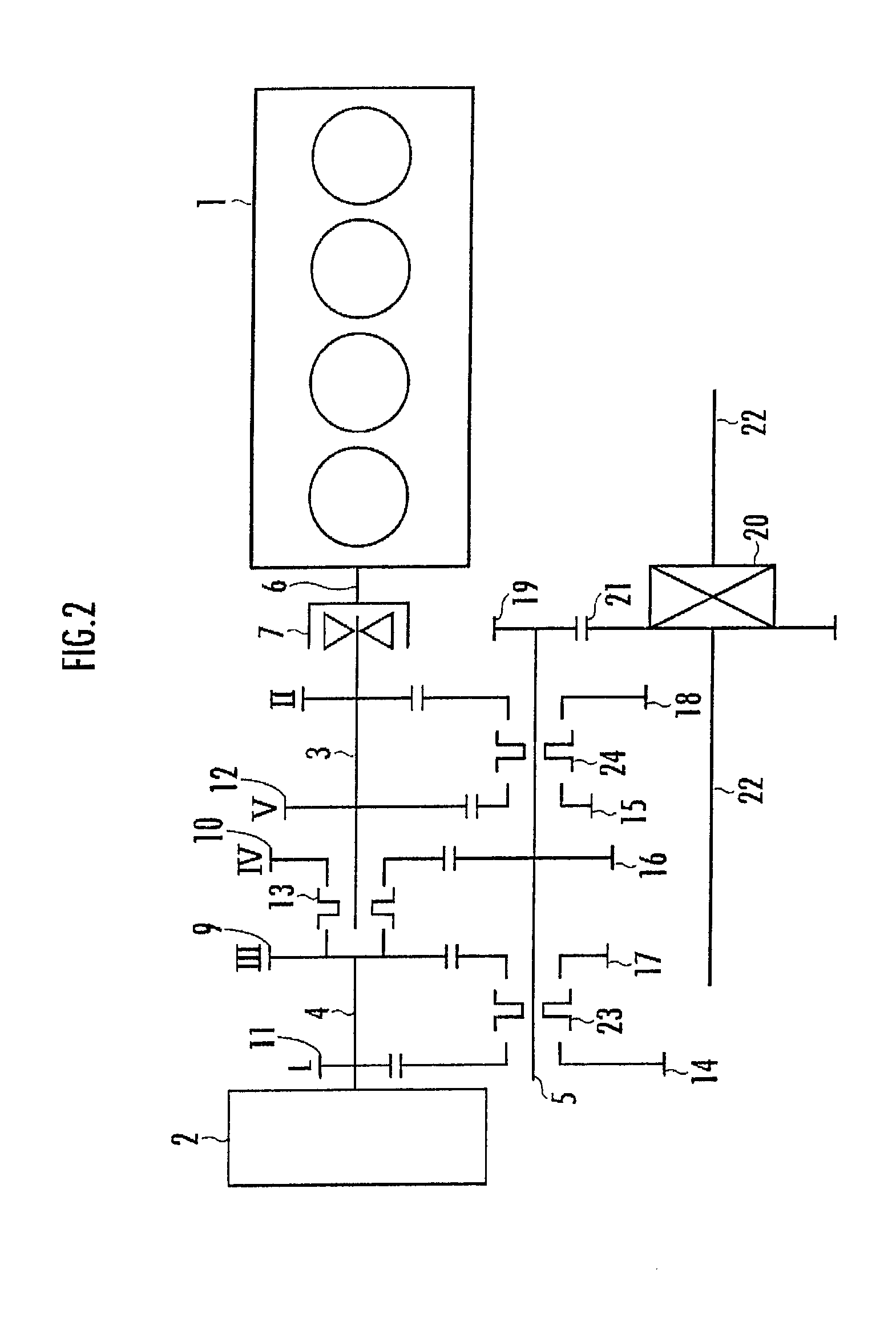
[0039]Further, in a fourth embodiment illustrated in FIG. 4, each of a first connecting unit 13 and a third connecting unit 24 may be provided with a one-way clutch. More specifically, the first connecting unit 13 may be divided into two portions, one portion being adjacent to a fifth-speed drive gear 12 and the other portion being adjacent to a fourth-speed drive gear 10, and one-way clutches 25a and 25b may be interposed between each of the two portions and a first input shaft 3. Similarly, the third connecting unit 24 may be divided into two portions, one portion being adjacent to a second-speed drive gear 8 and the other portion being adjacent to a third-speed drive gear 9, and one-way clutches 26a and 26b may be interposed between each of the two portions and the first input shaft 3. This arrangement permits a shortened gear shifting time. More specifically, in the case of, for example, the configuration illustrated in FIG. 1, to shift from the second-speed gear shift stage II ...

fifth embodiment

[0040]Further, in contrast to the configuration illustrated in FIG. 4, illustrated in FIG. 5, the position of a third-speed drive gear 9 and the position of a fourth-speed drive gear 10 are switched, and one-way clutches 27 and 28 are provided without dividing each of a first connecting unit 13 and a third connecting unit 24. This arrangement makes it possible to simplify the configurations of the first connecting unit 13 and the third connecting unit 24 and to provide the same advantages as those obtained by the configuration illustrated in FIG. 4.


PUM


Abstract

Provided is a transmission for a hybrid vehicle which permits a compact, lightweight structure and yet allows the power of an internal combustion engine to be disconnected and which is capable of efficiently transmitting power without complicating the control. The transmission includes a speed changing unit which has a first input shaft 3 connected to a power shaft 6 of an internal combustion engine 1 and a second input shaft 4 connected to a power shaft of a motor 2 and which establishes a plurality of gear shift stages. A one-way clutch 7 is interposed between the power shaft 6 of the internal combustion engine 1 and the first input shaft 3. The one-way clutch 7 disengages the connection between the power shaft 6 of the internal combustion engine 1 and the first input shaft 3 when the rotational speed of the power shaft 6 of the internal combustion engine 1 is lower than the rotational speed of the first input shaft. 3.

Description

TECHNICAL FIELD[0001]The present invention relates to a transmission for a hybrid vehicle which has an internal combustion engine and an electric motor.BACKGROUND ART[0002]The transmission of this type for a hybrid vehicle transmits the power of an engine (internal combustion engine) or the power of a motor (electric motor) to the drive shafts of wheels through the intermediary of a speed changing unit. Further, depending on the traveling state of a vehicle or a selected gear shift stage in a speed changing unit, the power of the motor is added to the power of the engine and the combined power is transmitted to the drive shafts, or either one of the power of the engine or the power of the motor is used to drive the vehicle.[0003]Meanwhile, in the case where a power shaft which outputs the revolution of the engine and an input shaft through which the power is input to a speed changing unit are in constant engagement, if, for example, the vehicle is caused to take off (start) only usi...

Claims


Application Information

Patent Timeline
Patent Type & Authority Applications(United States)
IPC IPC(8): F16H37/06
CPCB60K6/383Y10T74/19051B60K2006/4841B60K2006/541B60L2240/441B60L2240/486B60W10/02B60W10/06B60W10/08B60W10/113B60W20/00B60W2510/0638B60W2510/1015Y02T10/6221Y02T10/6286B60K6/48B60L50/61B60L50/16Y02T10/62Y02T10/7072Y02T10/70B60W20/15
Inventor SHIBAHATA, YASUJI
Owner HONDA MOTOR CO LTD
Why Eureka
Try Eureka