

Cylindrical sputtering target, and method for manufacturing same
- Summary
- Abstract
- Description
- Claims
- Application Information
AI Technical Summary
Benefits of technology
Problems solved by technology
Method used
Image

Examples
example 1
[0040]Twelve ITO cylindrical target materials (each having an outer diameter of 150 mm, an inner diameter of 133 mm, and a length of 260 mm) were prepared and masked with a heat-resistant tape except for their bonding surfaces, and the bonding surfaces were undercoated with In solder by a ultrasonic soldering iron. On the other hand, one cylindrical base made of SUS (having an outer diameter of 130 mm, an inner diameter of 120 mm, and a length of 3200 mm) was prepared and masked with a heat-resistant tape except for the bonding surface in order to prevent the bonding material from attaching to the surfaces other than the bonding surface, and the bonding surface was undercoated with the In solder by the ultrasonic soldering iron.
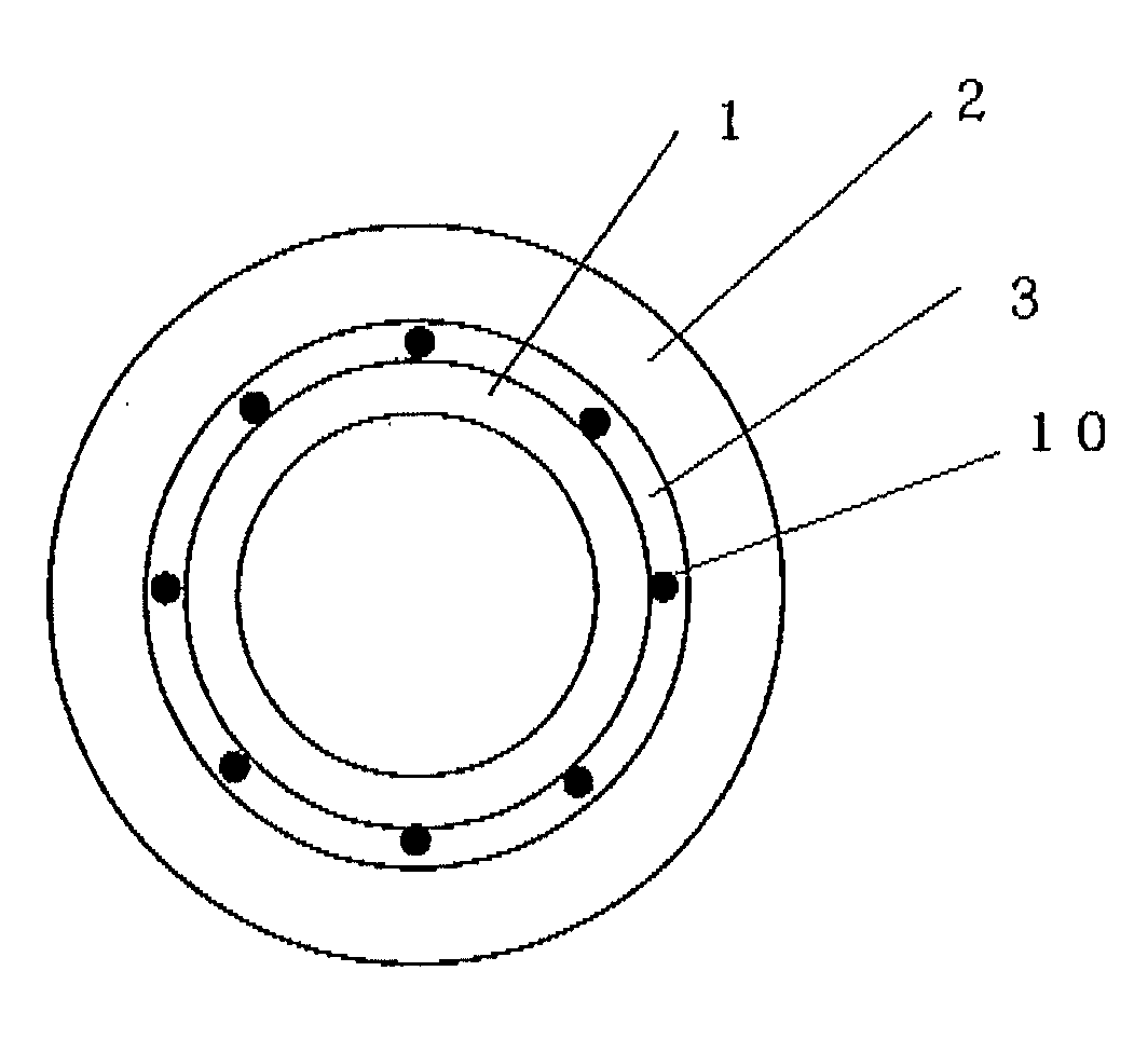
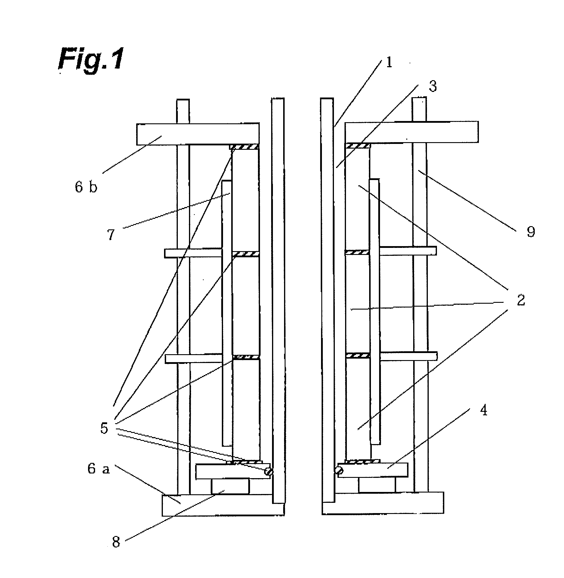
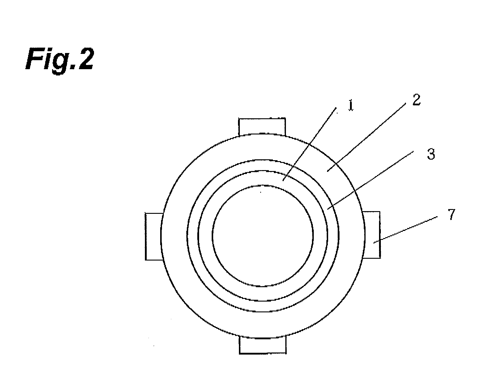
[0041]Then, thus processed cylindrical base 1 and 12 cylindrical target materials 2, the sealing jig 4 made of duralumin, the base supports 6a, 6b, the target support 7, and the block 8 were assembled as in FIG. 1. First, the cylindrical base 1 was arranged o...
example 2
[0046]Two ITO cylindrical target materials (each having an outer diameter of 93.0 mm, an inner diameter of 78.5 mm, and a length of 175 mm) were prepared and masked with a heat-resistant tape except for their bonding surfaces, and the bonding surfaces were undercoated with the In solder by the ultrasonic soldering iron. On the other hand, one cylindrical base made of SUS (having an outer diameter of 75.5 mm, an inner diameter of 70 mm, and a length of 490 mm) was prepared and masked with a heat-resistant tape except for the bonding surface in order to prevent the bonding material from attaching to the surfaces other than the bonding surface, and the bonding surface was undercoated with the In solder by the ultrasonic soldering iron. Thereafter, a target I having the divided portion listed in Table 1 was made by the same method as with Example 1 except for using the two cylindrical target materials. Targets II to IV having their corresponding divided portions listed in Table 1 were a...
PUM
| Property | Measurement | Unit |
|---|---|---|
| Length | aaaaa | aaaaa |
| Length | aaaaa | aaaaa |
| Length | aaaaa | aaaaa |
Abstract
Description
Claims
Application Information