Debris Separation Device and Method of Use

Inactive Publication Date: 2011-10-06
EXXON RES & ENG CO
View PDF4 Cites 27 Cited by
  • Summary
  • Abstract
  • Description
  • Claims
  • Application Information

AI Technical Summary

Benefits of technology

[0037]wherein debris separation device provides effective screening of the entire diameter of the fluidized catalytic cracking unit vessel at the plane in the flu

Problems solved by technology

This results in an increase in the temperature of the catalyst and the generation of a large amount of hot gas which is removed from the regeneration zone as a gas stream referred to as a flue gas stream.
However, the catalyst particles employed in a FCC process have a large surface area, which is due to a significant amount of pores located in the particles.
Although the quantity of hydrocarbons retained on each individual catalyst particle is very small, the large amount of catalyst and the high catalyst circulation rate which is typically used in a modern FCC process results in a significant quantity of hydrocarbons being withdrawn from the

Method used


Image

  • Debris Separation Device and Method of Use
  • Debris Separation Device and Method of Use
  • Debris Separation Device and Method of Use

Examples


Embodiment Construction

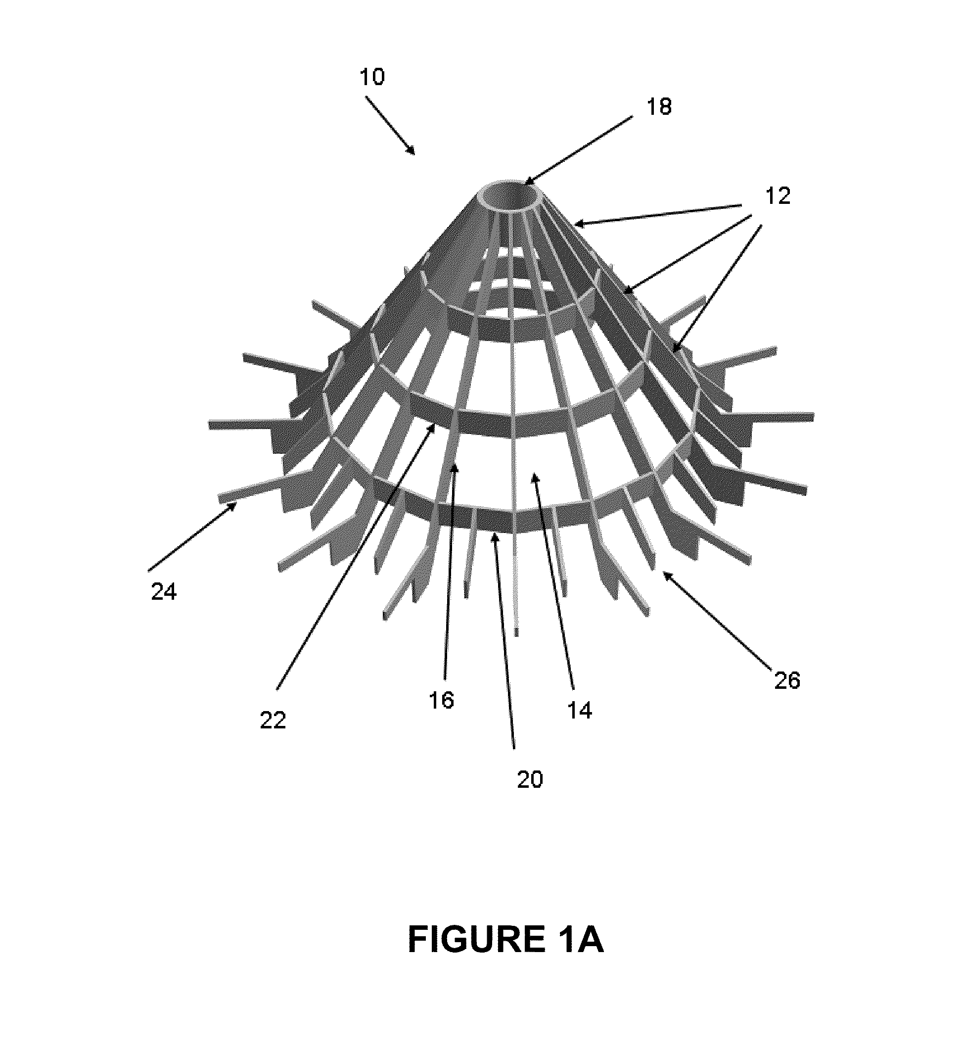
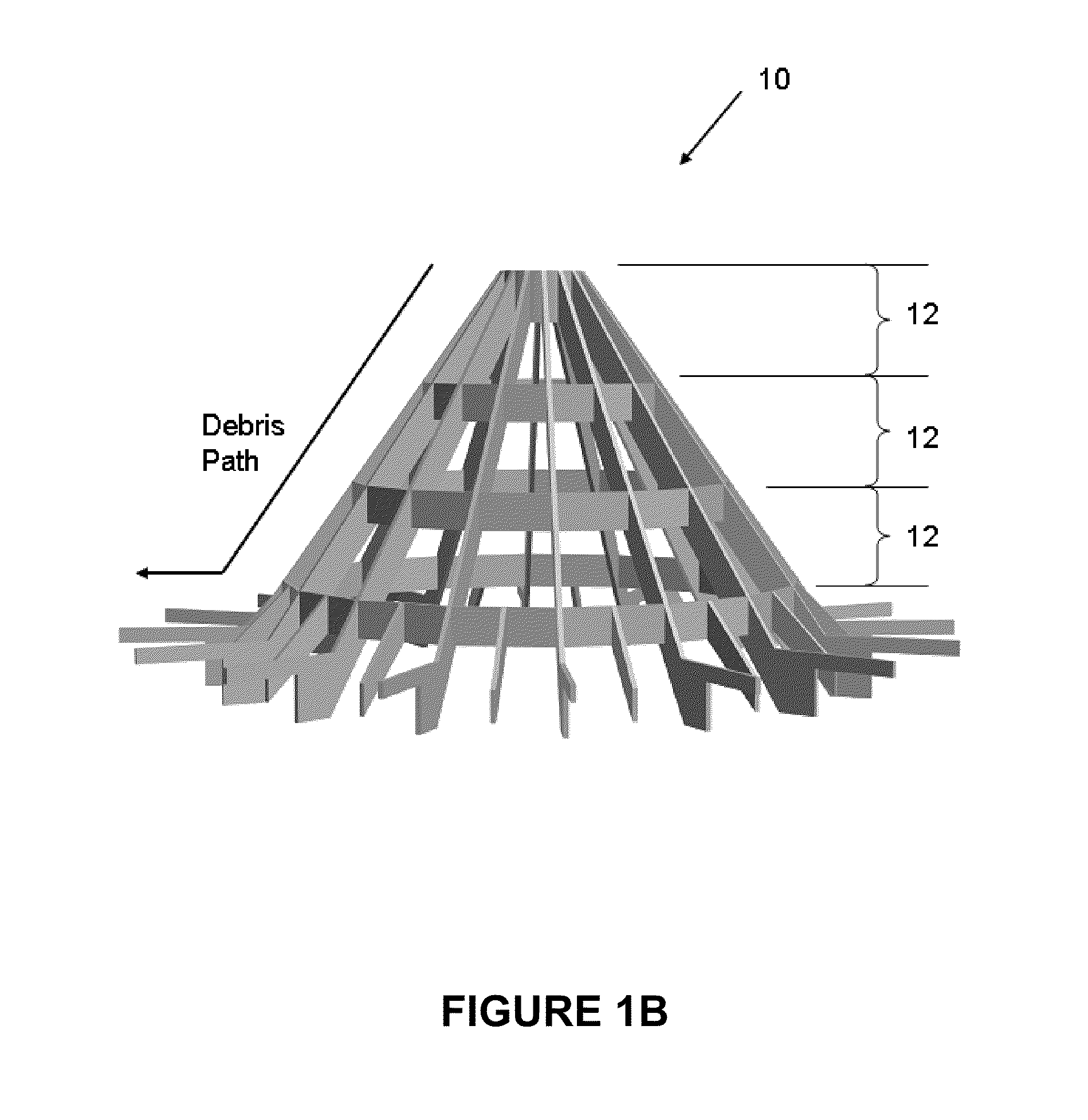
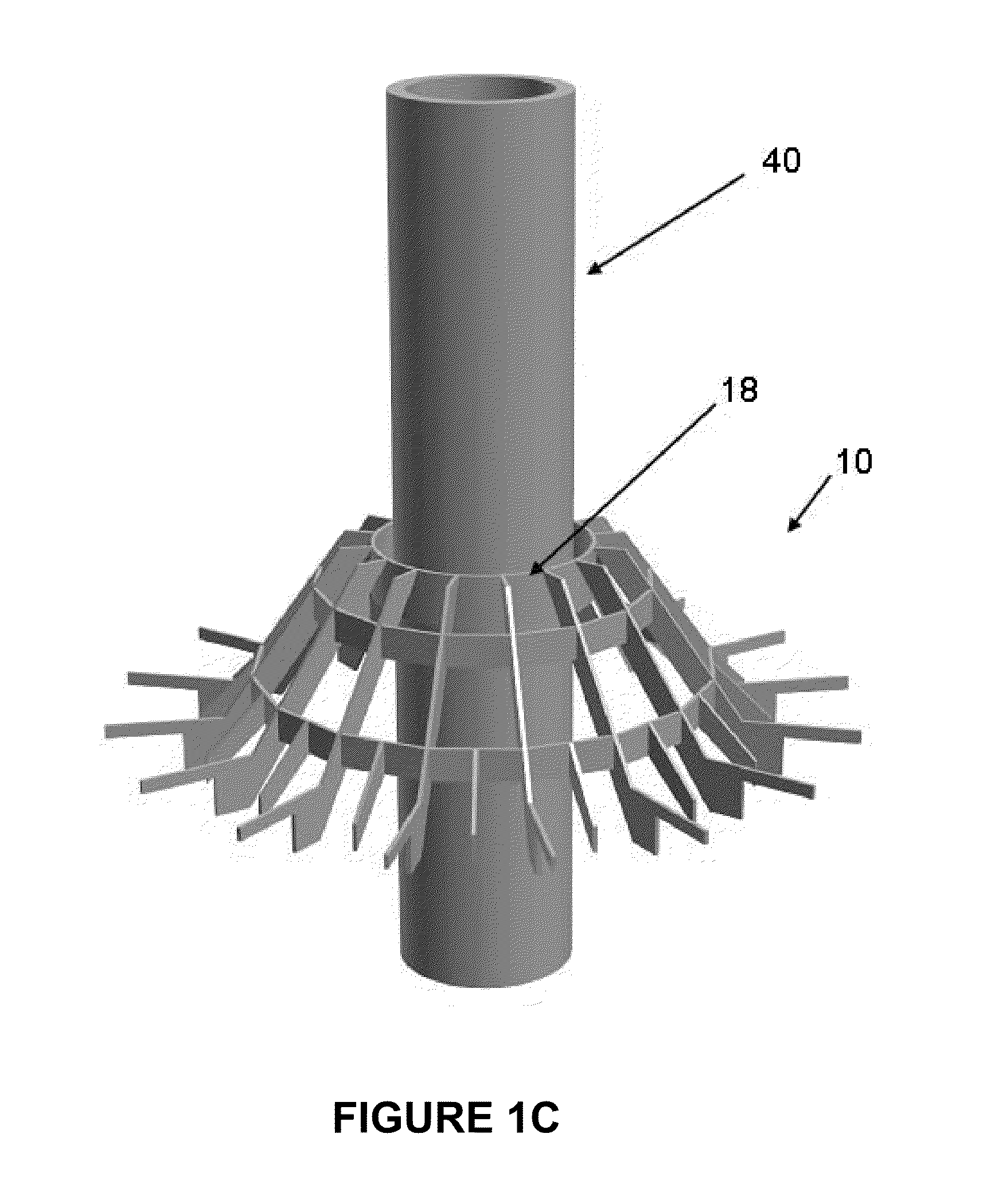
[0048]This disclosure relates to improved internal separation and collection components for use in a fluid solids reactor unit, more particularly downstream to the systems gaseous stream and catalyst / hydrocarbon separation zone (i.e., stripper zone). The separation and collection device of this disclosure affords improved control of coke accumulations that form upstream to the device location. A feature of this disclosure is to maintain a level of operating throughput as coke deposits are collected. The mechanical design of the device allows it to be implemented into either a fluidized catalytic cracking (or “FCC”) vessel cone or cylindrical sections.

[0049]In a typical FCC process in which the separation and collection devices of this disclosure may be used, the typical feed to a FCC unit is a gas oil such as a light or vacuum gas oil. Other petroleum-derived feed streams to a FCC unit may comprise a diesel boiling range mixture of hydrocarbons or heavier hydrocarbons such as reduce...


PUM


Abstract

A device for use in separating debris from a flowing stream which comprises a substantially hollow, substantially conical shaped structure comprising a top end member and a plurality of adjacently positioned side members angularly extending from a top end member to a substantially circular bottom end. The top end member has a smaller diameter than the circular bottom end. The adjacently positioned side members are configured to provide multiple tiers in a vertical plane in the conically shaped structure. The multiple tiers comprise a plurality of apertures in a horizontal plane in the conically shaped structure. The plurality of apertures are configured for separating large debris particles, generally formed from coke and spent catalyst, from a flowing fluidized catalytic cracking stream, and directing the captured debris toward the circular bottom end of the device. A method of separating debris from a flowing stream is also provided. In particular, the device and method are useful for separating coke deposits in a fluidized catalytic cracking (FCC) process.

Description

[0001]This application claims the benefit of U.S. Provisional Application No. 61 / 341,361 filed Mar. 30, 2010.FIELD OF THE DISCLOSURE[0002]This disclosure relates to devices for use in separating debris, e.g., coke, from a flowing stream, e.g., a hydrocarbon or hydrocarbon / catalyst stream in a fluidized catalytic cracking (FCC) process, and to methods of separating debris from a flowing stream.DISCUSSION OF THE BACKGROUND ART[0003]A variety of processes contact finely divided particulate material with a hydrocarbon containing feed under conditions wherein a fluid maintains the particles in a fluidized condition to effect transport of the solid particles to different stages of the process. FCC is an example of such a process that contacts hydrocarbons in a reaction zone with a catalyst composed of finely divided particulate material.[0004]A FCC unit comprises a reaction zone and a catalyst regeneration zone. In the reaction zone, a feed stream is contacted with finely divided fluidize...

Claims


Application Information

Patent Timeline
IPC IPC(8): C10G31/00B01J8/00
CPCB01J8/0065B01J8/388B01J2208/00672C10G2300/70C10G11/18C10G31/10C10G2300/208B01J2208/0084
Inventor TAMMERA, ROBERT F.RIGANO, DOMINIC C.
Owner EXXON RES & ENG CO
Why Eureka
Try Eureka