
Chemical supply system

Active Publication Date: 2011-10-06
CKD
View PDF4 Cites 4 Cited by
  • Summary
  • Abstract
  • Description
  • Claims
  • Application Information

AI Technical Summary

Benefits of technology

[0010]Accordingly, an object of the present invention is to solve at least a part of the conventional problems described above with a technique for reducing the effect of hydraulic head pressure in a chemical supply system.

Problems solved by technology

However, in such a configuration, the system should be changed on both the chemical tank side and the chemical supply pump side, and the number of changes required for the already existing systems is large.
Further, a configuration can be also considered in which a needle valve is provided at a position on the chemical tank side, rather than the chemical supply pump side, a throttle amount is manually adjusted, and the effect of hydraulic head pressure is reduced, but in this case the effect of hydraulic head pressure cannot be reduced automatically.

Method used


Image

  • Chemical supply system
  • Chemical supply system
  • Chemical supply system

Examples


first embodiment

A. First Embodiment

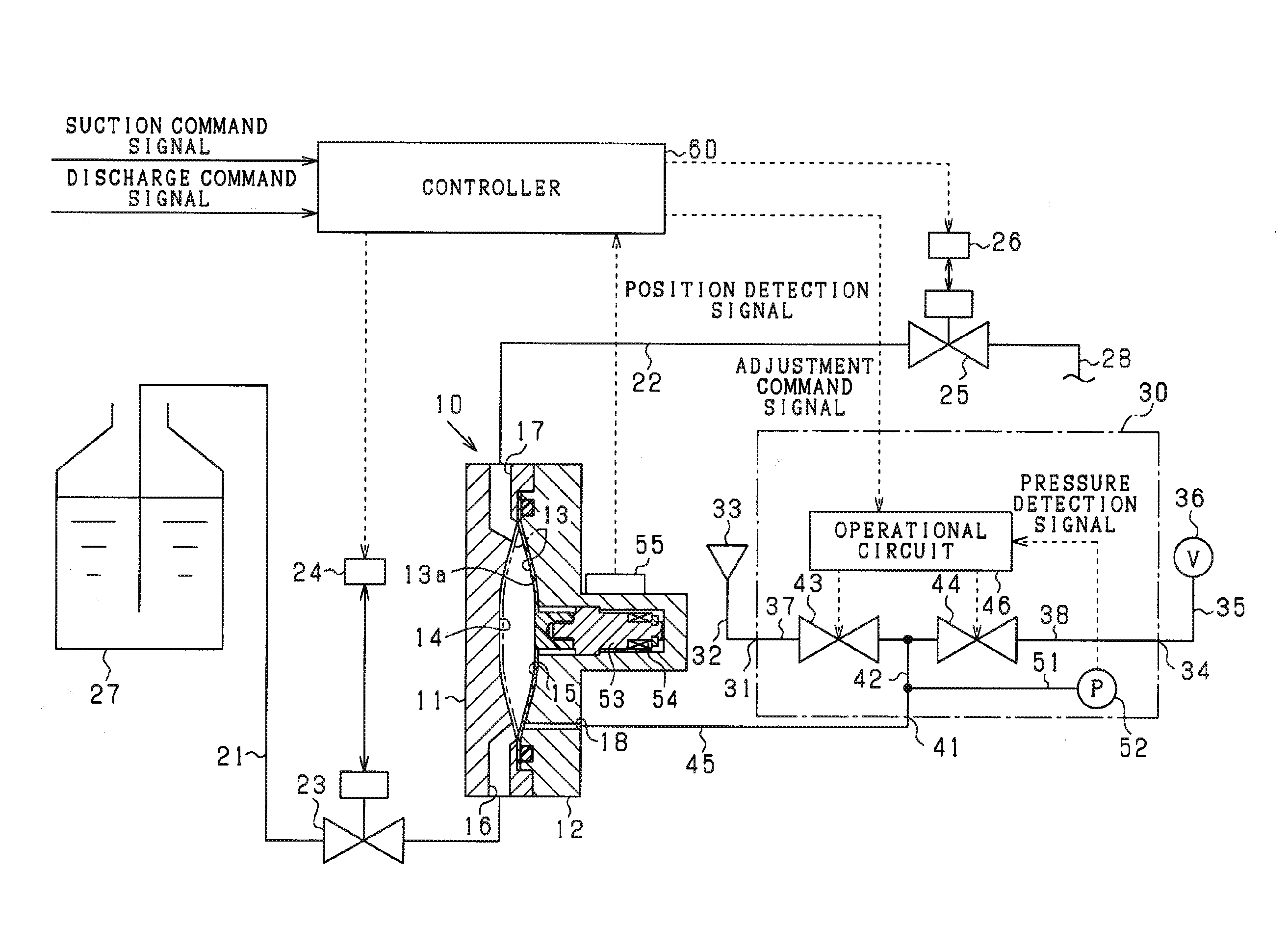
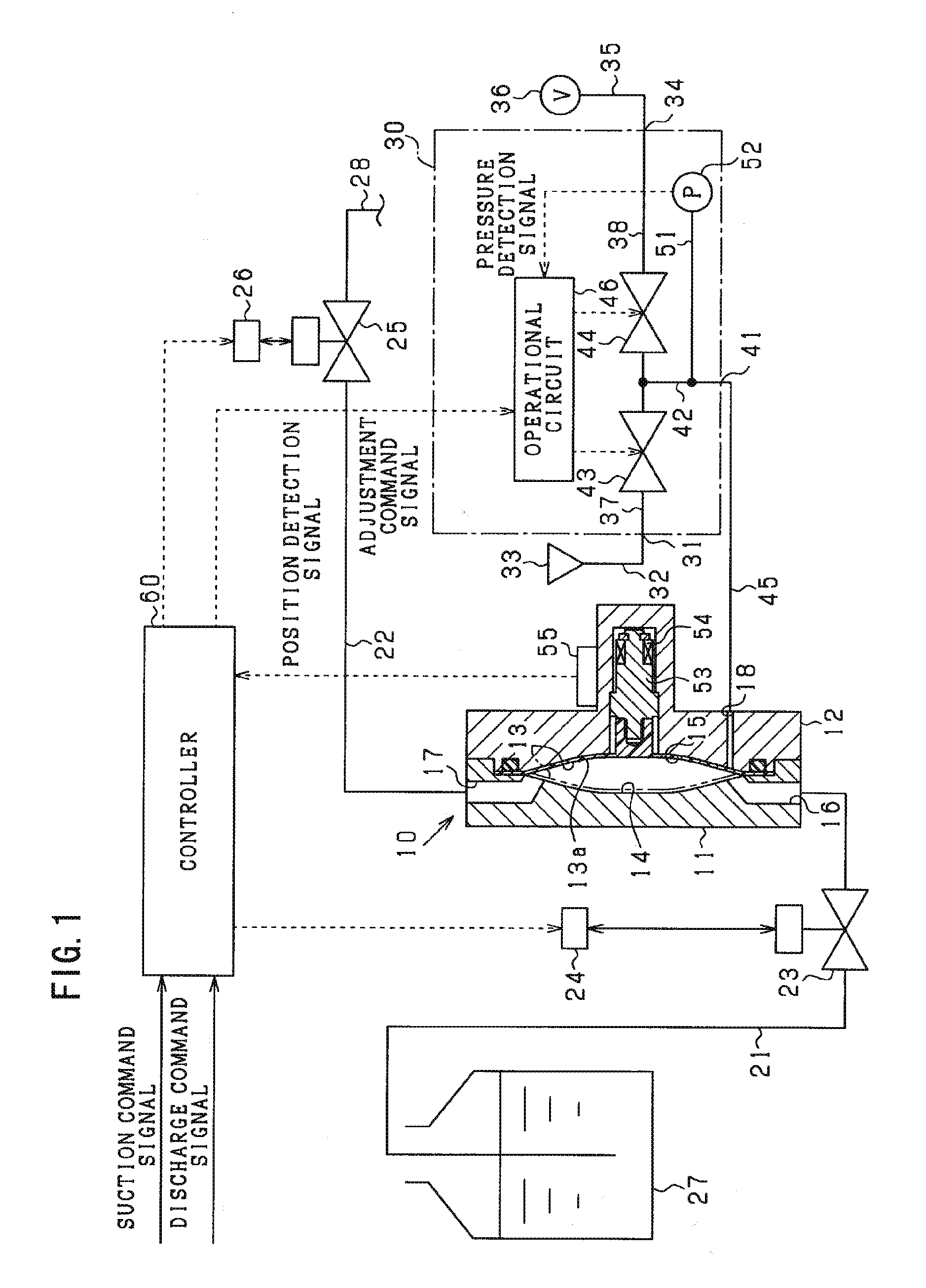
[0021]The first embodiment of the present invention will be described below with reference to the appended drawings. The present embodiment relates to a chemical supply system that is used in a production line of semiconductor devices or the like. The basic configuration of the system will be explained below with reference to FIG. 1.

[0022]The chemical supply system shown in FIG. 1 includes a chemical supply pump 10 for sucking in and discharging a chemical solution. The chemical supply pump 10 has two (left and right) divided bodies 11, 12, and recesses are formed in opposing surfaces of these bodies 11, 12. A diaphragm 13 composed of a flexible film is inserted as a volume-changing member between the bodies 11, 12, and the circumferential edge of the diaphragm 13 is clamped by the bodies 11, 12. In this case, the space in the recesses of the bodies 11, 12 is partitioned by a partition region 13a of the diaphragm 13, a pump chamber 14 is formed between the recess ...

second embodiment

B. Second Embodiment

[0051]In the present embodiment, the configuration used to eliminate the effect of hydraulic head pressure of the chemical tank 27 in the chemical solution suction operation is different from that of the first embodiment. The difference between the two configurations will be described below.

[0052]The chemical supply system of the present embodiment is basically similar to that shown in FIG. 1. However, when a set value of suction pressure is determined, a detection result of the position detection sensor 55 is used instead of a detection result of the pressure sensor 52.

[0053]FIG. 4 shows the contents of computations performed in the controller 60 during suction of the chemical solution. The below-described operational processing is performed repeatedly with comparatively short intervals during suction of the chemical solution.

[0054]A target displacement rate read unit B1 reads from a nonvolatile memory of the controller 60 a target value of displacement rate in ...

third embodiment

C. Third Embodiment

[0066]In the present embodiment, the configuration used to eliminate the effect of hydraulic head pressure of the chemical tank 27 in the chemical solution suction operation is different from that of the first embodiment. The difference between the two configurations will be described below.

[0067]The chemical supply system of the present embodiment is basically similar to that shown in FIG. 1. However, the detection results of the pressure sensor 52 are not used to determine the set value of suction pressure and the configuration of the electropneumatic regulator 30 is different from that described above.

[0068]More specifically, as shown in FIG. 6, a flow rate sensor 71 is provided in the intermediate position of the discharge passage 38 of the electropneumatic regulator 30. Since the flow rate sensor 71 is provided, it is possible to detect the flow rate of the working air when the suction pressure is applied to the working chamber 15 of the chemical supply pump ...


PUM


Abstract

This invention provides a chemical supply system for supplying chemical solution from a chemical tank. The chemical supply system includes a chemical supply pump, a pressure adjuster configured to suction the chemical solution into the pump chamber by setting the pressure of working gas to a suction pressure, a switching controller configured to switch the suction-side opening-closing valve to the open state for starting to fill the pump chamber with the chemical solution, a pressure detector configured to detect at least one of a gas pressure in a space connected to the working chamber and a gas pressure in the working chamber when the suction-side opening-closing valve is switched to the open state and starts an inflow of the chemical solution to the pump chamber, and a suction controller configured to control the suction pressure applied to the working chamber by the pressure adjuster, based on a detection result of the pressure detector.

Description

CROSS-REFERENCE TO RELATED APPLICATIONS[0001]This application claims priorities of Japanese Patent Application No. 2010-78702 filed on Mar. 30, 2010 which is hereby incorporated by reference.BACKGROUND OF THE INVENTION[0002]1. Field of the Invention[0003]The present invention relates to a chemical supply system that supplies a chemical solution by using a chemical supply pump performing suction and discharge of the chemical solution by volume changes inside the pump chamber.[0004]2. Description of the Related Art[0005]In a process using a chemical solution in a semiconductor fabrication apparatus, a chemical supply system such as described in Japanese Patent Application Publication No. 2006-46284 has been suggested for coating a chemical solution such as a photoresist solution in predetermined amounts on a semiconductor wafer.[0006]In the chemical supply system described in Japanese Patent Application Publication No. 2006-46284, a chemical supply pump is provided for sucking the che...

Claims


Application Information

Patent Timeline
IPC IPC(8): B67D1/00B65D88/54
CPCF04B43/073B05C11/1013B05C11/1026F04B43/14G03F7/16G03F7/2041H01L21/0274
Inventor NAGASAKI, ISAOITO, AKIHIROTOYODA, TETSUYA
Owner CKD
Features
  • Generate Ideas
  • Intellectual Property
  • Life Sciences
  • Materials
  • Tech Scout
  • Unparalleled Data Quality
  • Higher Quality Content
  • 60% Fewer Hallucinations
Learn More