Display and display panel thereof

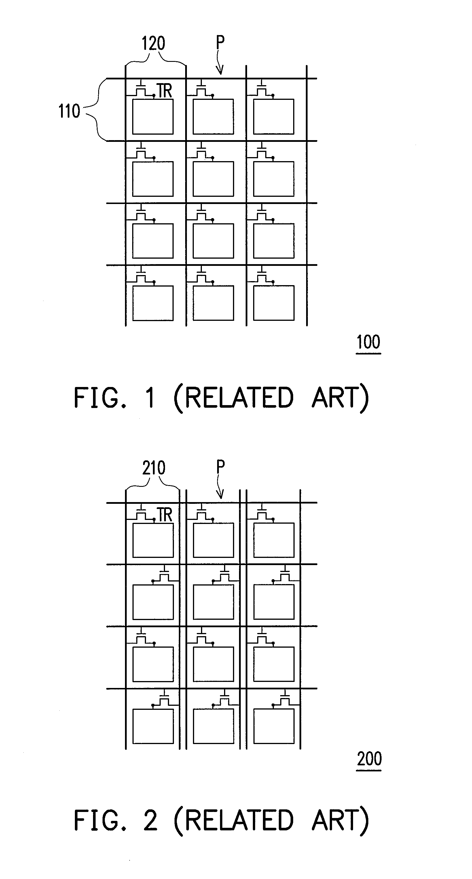
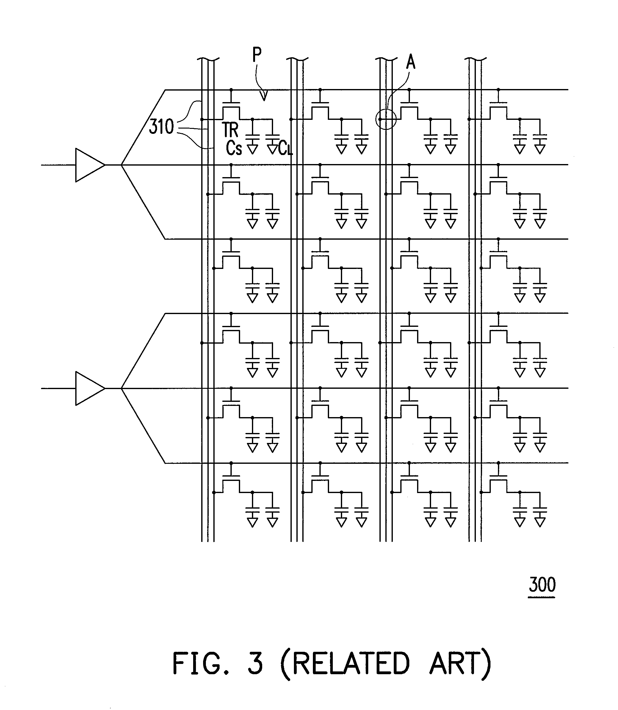
a display panel and display panel technology, applied in the direction of discharge tube/lamp details, electric discharge tubes, instruments, etc., can solve the problems of insufficient charge of each pixel p, image distortion, and inability to display the correct grayscale, so as to avoid the production of cross-over capacitance caused by lines crossing

Active Publication Date: 2011-10-06
AU OPTRONICS CORP
View PDF2 Cites 31 Cited by
  • Summary
  • Abstract
  • Description
  • Claims
  • Application Information

AI Technical Summary

Benefits of technology

As described above, the present invention provides a display and a display panel thereof. A plurality of data lines of the display panel are grouped into a plurality of groups, and the data lines in each of the groups are adjacent to each other and do not cross over any pixel. In each of the groups, a portion of the data lines cross over a portion of the scan lines, and the rest data lines cross over all the scan lines. Thus, each of the pixels in each pixel column is coupled to a portion of data lines in two groups, and the pixels are directly coupled to the data lines without crossing. Thereby, the production of cross-over capacitances caused by lines crossing can be avoided, and accordingly the crosstalk to cause the local frame producing the color washout further could be prevented.

Problems solved by technology

However, if the frame rate is increased, the charge time of each pixel P will be too short and thus causing that each of the pixels P is charged insufficiently.
Because the charge time is too short, each pixel P cannot be charge to the appropriate voltage level and accordingly cannot display the correct grayscale (i.e., image distortion).
As a result, the image quality of the LCD is reduced.
However, this problem will be produced again if the frame rate is further increased or the resolution of the display panel is increased.
Herein, lines (i.e. data lines) crossing may result in unnecessary cross-over capacitances and accordingly the crosstalk may be produced to cause the local frame producing the color washout.
As a result, the cost of the display panel is increased.

Method used


Image

  • Display and display panel thereof
  • Display and display panel thereof
  • Display and display panel thereof

Examples


Embodiment Construction

Reference will now be made in detail to the present preferred embodiments of the invention, examples of which are illustrated in the accompanying drawings. Wherever possible, the same reference numbers are used in the drawings and the description to refer to the same or like parts.

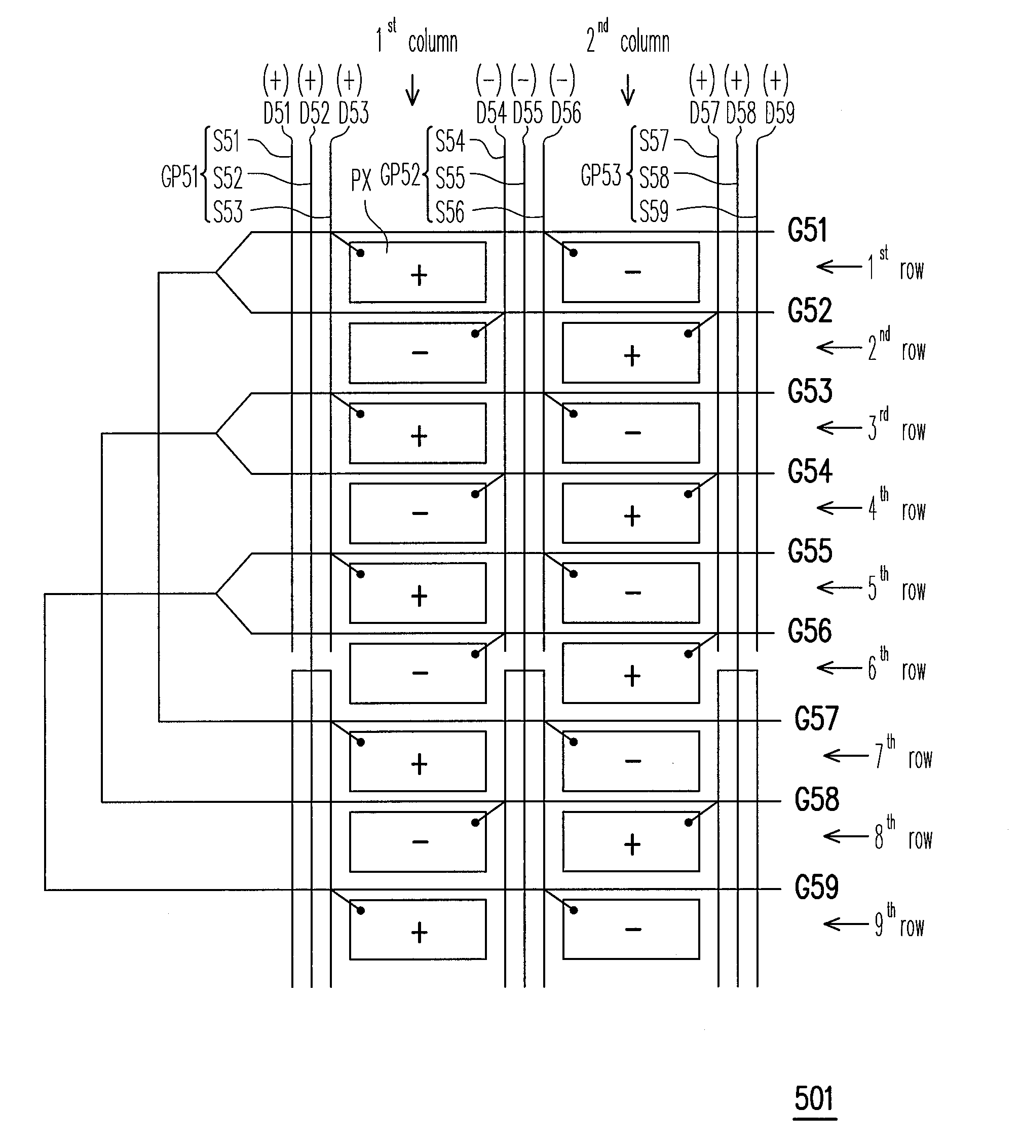
FIG. 5A is a system block diagram of a display 500 according to an embodiment of the present invention. Referring to FIG. 5A, the display 500 comprises a display panel 501, a gate driver 503, a source driver 505, a timing controller (T-con) 507, and a backlight module 509. The display 500 may be a thin film transistor (TFT)

LCD, and correspondingly, the display panel 501 is a TFT display panel.

The backlight module 509 provides a light source to the display panel 501. The T-con 507 controls the operations of the gate driver 503 and the source driver 505 so that the gate driver 503 and the source driver 505 respectively generate scan signals and data signals for driving the display panel 501.

FIG. 5B is a diag...


PUM


Abstract

A display panel including a plurality of scan lines, a plurality of data lines, and a plurality of pixels is provided. The data lines are disposed substantially perpendicular to the scan lines Each of the pixels is electrically connected with the corresponding data line and the corresponding scan line and the pixels are arranged as an array. The data lines are grouped into a plurality of groups and each of the groups is disposed between two adjacent pixel columns and has N data lines, where N is a positive integer greater than or equal to 3. A portion of the data lines of at least a first group among the groups cross over a portion of the scan lines. The rest data lines of the first group cross over all the scan lines.

Description

CROSS-REFERENCE TO RELATED APPLICATIONThis application claims the priority benefit of Taiwan application serial no. 99110141, filed on Apr. 1, 2010. The entirety the above-mentioned patent application is hereby incorporated by reference herein and made a part of specification.BACKGROUND OF THE INVENTION1. Field of the InventionThe present invention generally relates to a display and a display panel thereof, and more particularly, to a display with reduced crosstalk and a display panel thereof.2. Description of Related ArtIn recent years, many portable electronic products and flat panel display products have been developed along with the advancement of semiconductor technology. Among different types of flat panel displays, liquid crystal display (LCD) has become the mainstream of display products thanks to its many advantages, such as low-voltage operation, no scattering radiation, light weight, and small volume.FIG. 1 is a diagram of a display panel of a conventional LCD. As shown i...

Claims


Application Information

Patent Timeline
Patent Type & Authority Applications(United States)
IPC IPC(8): H01J21/10
CPCG09G3/3614G09G2310/0218G09G2310/0205G09G3/3648
Inventor HUANG, YU-SHENGHSU, YA-LINGHOU, HUNG-LUNG
Owner AU OPTRONICS CORP
Why Eureka
Try Eureka