Method for controlling permanent magnet synchronous motor

a technology of synchronous motors and permanent magnets, applied in the direction of electric generator control, dynamo-electric converter control, dynamo-electric gear control, etc., can solve the problems of large data storage, large time and effort, disadvantageous use of voltage and current generation command based on the map set at the reference voltage, etc., to improve the fuel efficiency of the vehicle and improve the voltage utilization of the motor-inverter system.

Active Publication Date: 2011-10-06
HYUNDAI MOTOR CO LTD +1
View PDF14 Cites 52 Cited by
  • Summary
  • Abstract
  • Description
  • Claims
  • Application Information

AI Technical Summary

Benefits of technology

[0016]In certain preferred embodiments, the present invention provides a method for controlling a permanent magnet synchronous motor, in which a battery voltage variation is suitably compensated in real time to improve the voltage utilization of a motor-inverter system and, in turn, suitably improve the fuel efficiency of the vehicle.

Problems solved by technology

Particularly, in the electric vehicles such as hybrid vehicles, fuel cell vehicles, and the like, since the battery voltage during operation of a vehicle drive motor is suitably higher than the reference voltage at which the map is set, the generation of the current command based on the map set at the reference voltage is disadvantageous in terms of the use of voltage and current.
However, it requires a large data storage as well as considerable time and effort.

Method used


Image

  • Method for controlling permanent magnet synchronous motor
  • Method for controlling permanent magnet synchronous motor
  • Method for controlling permanent magnet synchronous motor

Examples


Embodiment Construction

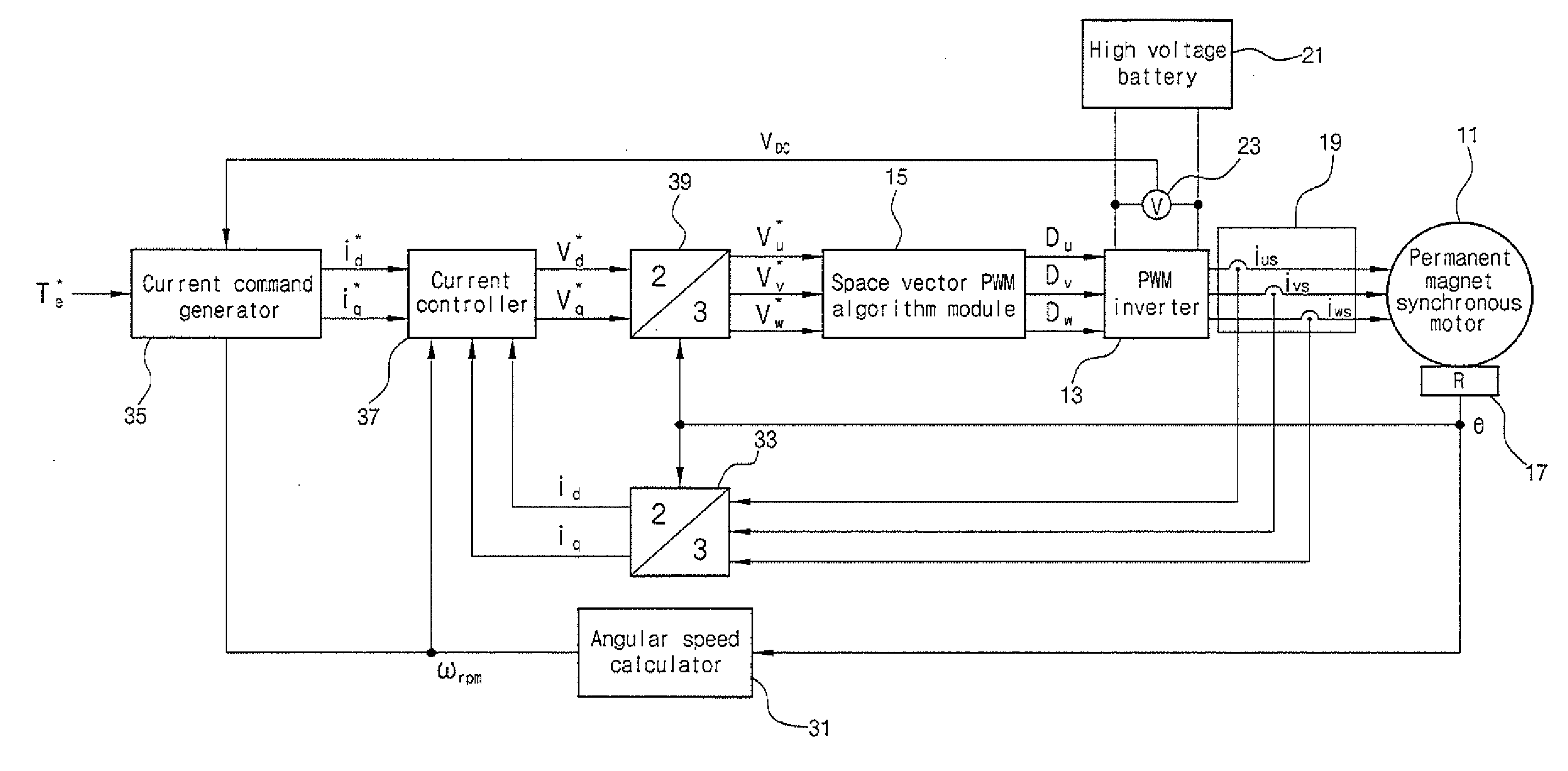
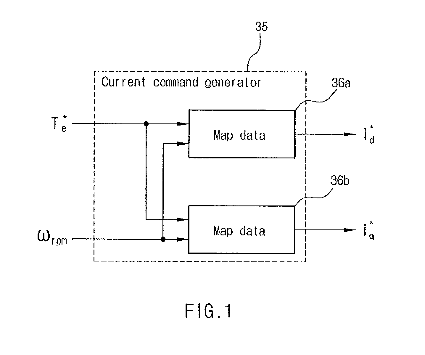
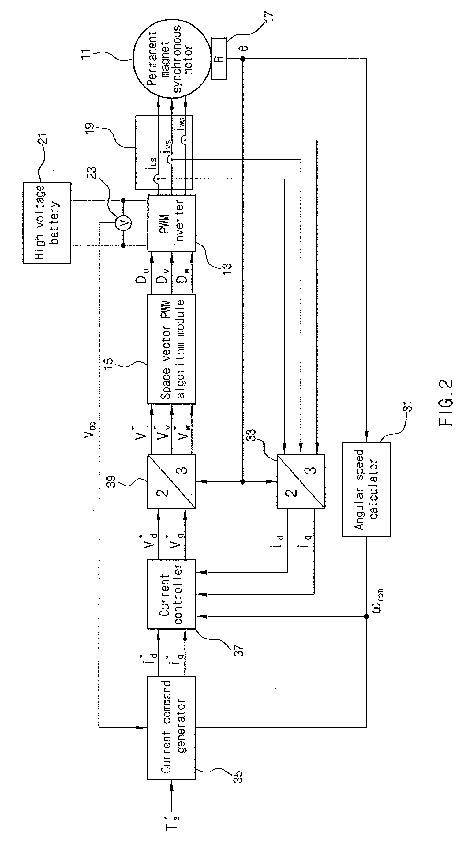
[0036]As described herein, the present invention features a method for controlling a permanent magnet synchronous motor, the method comprising detecting an absolute angular position of a permanent magnet synchronous motor, calculating a rotational speed of the permanent magnet synchronous motor based on the detected absolute angular position, detecting a voltage of a battery as a power source, calculating a compensated speed, wherein a battery voltage variation is compensated from the compensated speed, generating a d-axis current command and a q-axis current command corresponding to the torque command and the compensated speed using a predetermined current command map, converting three-phase currents flowing into the permanent magnet synchronous motor into a d-axis feedback current and a q-axis feedback current based on the detected absolute angular position, calculating a d-axis voltage command and a q-axis voltage command based on the d-axis current command, the q-axis current co...


PUM


Abstract

The present invention provides a method for controlling a permanent magnet synchronous motor used in electric vehicles such as hybrid vehicles, fuel cell vehicles, and the like. The method for controlling the permanent magnet synchronous motor preferably includes detecting an absolute angular position of a permanent magnet synchronous motor; calculating a rotational speed of the permanent magnet synchronous motor based on the detected absolute angular position; detecting a voltage of a battery as a power source; calculating a compensated speed, for which a battery voltage variation is compensated, from the rotational speed of the permanent magnet synchronous motor based on a torque command, the rotational speed of the permanent magnet synchronous motor, and the battery voltage; generating a d-axis current command and a q-axis current command corresponding to the torque command and the compensated speed using a predetermined current command map; converting three-phase currents flowing into the permanent magnet synchronous motor into a d-axis feedback current and a q-axis feedback current based on the detected absolute angular position; calculating a d-axis voltage command and a q-axis voltage command based on the d-axis current command, the q-axis current command, the d-axis feedback current, and the q-axis feedback current; converting the d-axis voltage command and the q-axis voltage command into three-phase voltage commands based on the detected absolute angular position; and controlling the operation of the permanent magnet synchronous motor based on the three-phase voltage commands.

Description

CROSS-REFERENCE TO RELATED APPLICATION[0001]This application claims under 35 U.S.C. §119(a) the benefit of Korean Patent Application No. 10-2010-0029169 filed Mar. 31, 2010, the entire contents of which are incorporated herein by reference.BACKGROUND[0002](a) Technical Field[0003]The present disclosure relates, generally, to a method for controlling a motor. More particularly, it relates to a method for controlling a permanent magnet synchronous motor that is used in electric vehicles such as hybrid vehicles, fuel cell vehicles, and the like.[0004](b) Background Art[0005]A permanent magnet synchronous motor (PMSM) is a high-power and high-efficiency motor that is widely used in the fields of electric vehicles including hybrid vehicles, fuel cell vehicles, and the like, as well as other industries.[0006]In particular, an interior permanent magnet synchronous motor (IPMSM) is a synchronous motor having a permanent magnet inserted into a rotor iron core. The IPMSM has excellent high-sp...

Claims


Application Information

Patent Timeline
Patent Type & Authority Applications(United States)
IPC IPC(8): H02P21/14H02P21/00B60L9/18H02P27/04
CPCY02T10/7258H02P21/14B60L3/12B60L15/025B60L50/13B60L2220/14B60L2240/421B60L2240/423B60L2240/427B60L2240/429B60L2240/527B60L2240/529B60L2260/44Y02T10/64Y02T10/7072Y02T10/72B60L9/18B60L15/20B60L50/16B60L2220/58B60Y2200/91B60Y2200/92H02P5/00H02P6/04H02P21/00Y02T10/70
Inventor KIM, BUM SIKLEE, YOUNG KOOKJUNG, JIN HWAN
Owner HYUNDAI MOTOR CO LTD
Why Eureka
Try Eureka