Control apparatus for permanent magnet motor

a control apparatus and permanent magnet technology, applied in the direction of motor/generator/converter stopper, dynamo-electric gear control, dynamo-electric converter control, etc., can solve the problem that the method cannot be directly applied to the salient pole type, and achieve accurate torque control characteristics

Inactive Publication Date: 2011-10-06
KOKUSAN DENKI CO LTD
View PDF6 Cites 32 Cited by
  • Summary
  • Abstract
  • Description
  • Claims
  • Application Information

AI Technical Summary

Benefits of technology

[0029]According to the present invention, in a control apparatus for a permanent magnet motor, the torque ripple of the magnet motor wherein there is a reluctance torque is suppressed. Moreover, the “ripple component” and “DC component” of the torque ripple can be arbitrarily controlled in a predetermined relationship, and accurate torque control characteristics can be realized.

Problems solved by technology

Therefore, this method cannot be directly applied to the salient pole type (Ldq) magnet motor.

Method used


Image

  • Control apparatus for permanent magnet motor
  • Control apparatus for permanent magnet motor
  • Control apparatus for permanent magnet motor

Examples


first embodiment

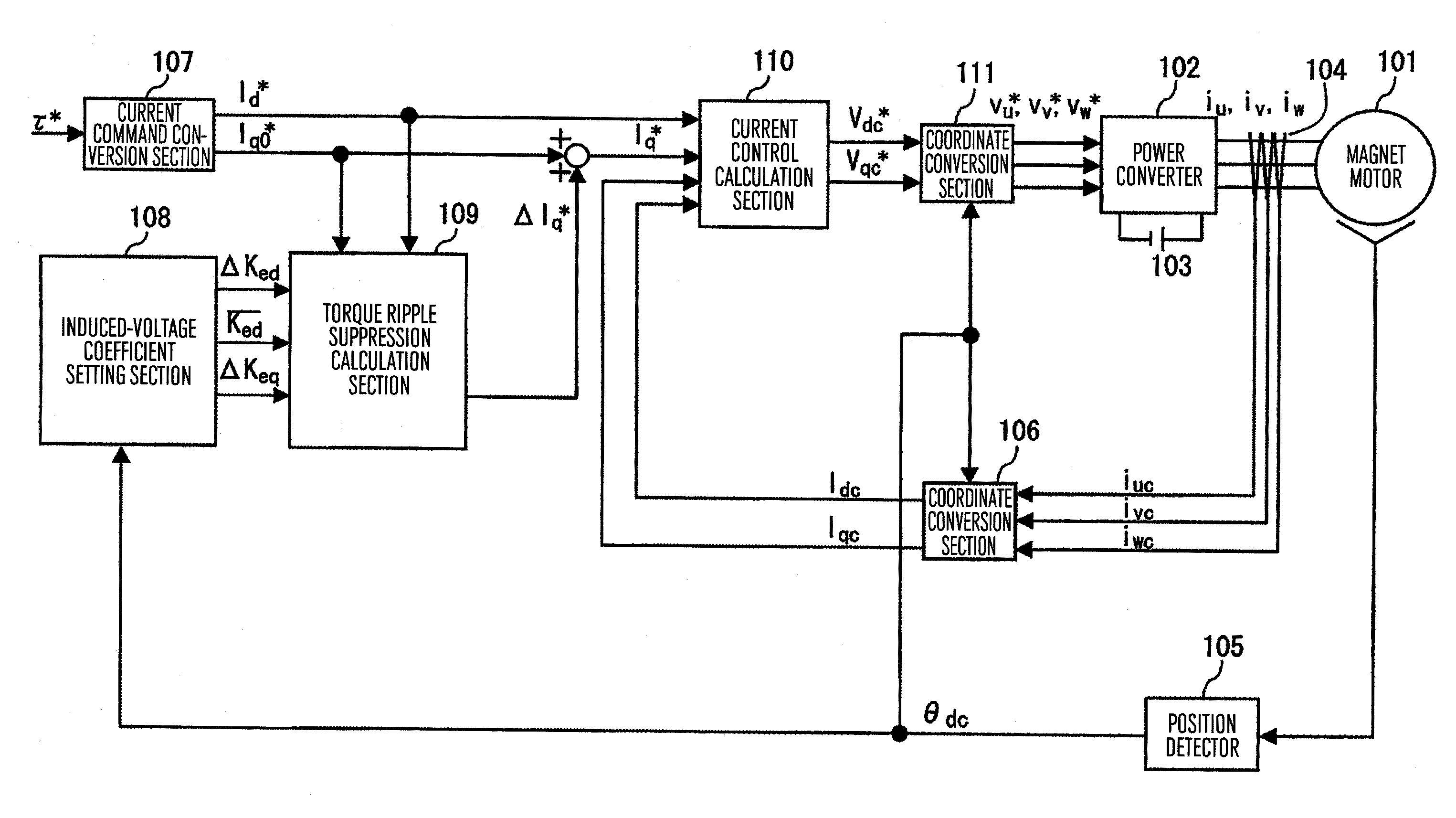
[0047]FIG. 1 illustrates a configuration example of a control apparatus for a permanent magnet motor according to one embodiment of the present invention.

[0048]A magnet motor 101 outputs a combined torque of a magnetic flux torque component of the magnetic flux of a permanent magnet and a reluctance torque component of the inductance of an armature coil.

[0049]A power converter 102 outputs the voltages proportional to three-phase AC voltage command values Vu*, Vv*, Vw* and varies the output voltage and rotational speed of the magnet motor 101.

[0050]ADC power supply 103 supplies a DC voltage to the power converter 102.

[0051]A current detection section 104 detects three-phase AC currents iu, iv, iw flowing into the magnet motor 101, and outputs current detection values iuc, ivc, iwc.

[0052]A position sensor 105 is a resolver or encoder capable of detecting a position θ of the motor, and outputs a position detection value θdc.

[0053]A coordinate conversion section 106 calculates current d...

second embodiment

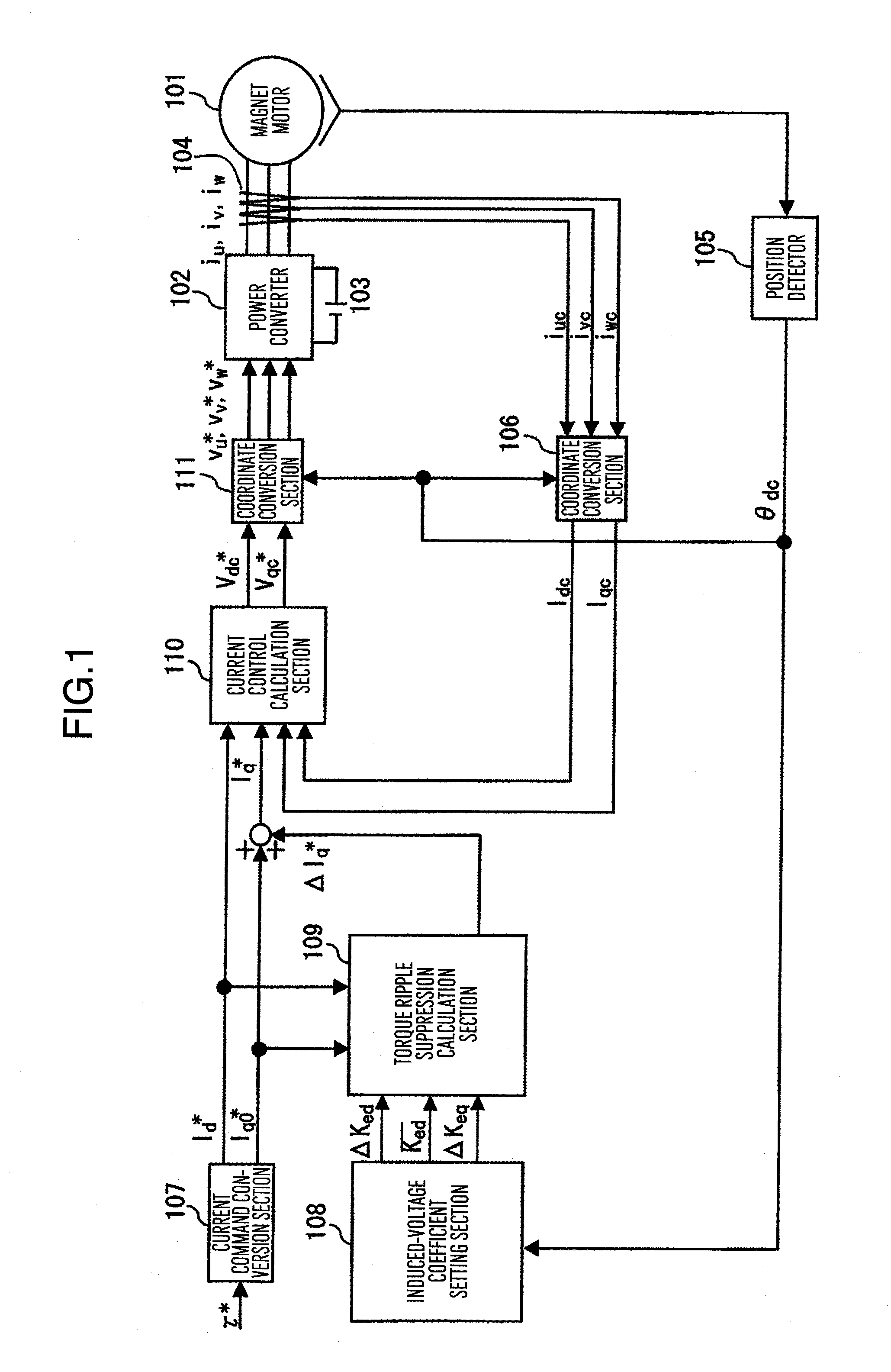
[0104]FIG. 10 illustrates another embodiment of the present invention.

[0105]In the first embodiment, the current control calculation is performed on the d-axis and q-axis of the rotating coordinate system, while in this embodiment, the current control calculation in the three-phase AC (u, v, w) of the fixed coordinate system is performed.

[0106]In this diagram, unless otherwise stated, the individual constituent element is the same as that of FIG. 1.

[0107]A coordinate conversion section 111a receives the current command value Id* of the d-axis, and Iq* which is the added value of the ripple current command value ΔIq* of the q-axis (i.e., the output of the torque ripple calculation section 109), and the current command value Iqo* of the q-axis (i.e., the output of current command conversion section 107), and calculates the three-phase AC current command values (iu*, iv*, iw*) according to Formula (21) and output the same.

[iu*iv*iw*]=[10-1 / 23 / 2-1 / 2-3 / 2]·[cos(θdc)-sin(θdc)sin(θdc)cos(θd...

third embodiment

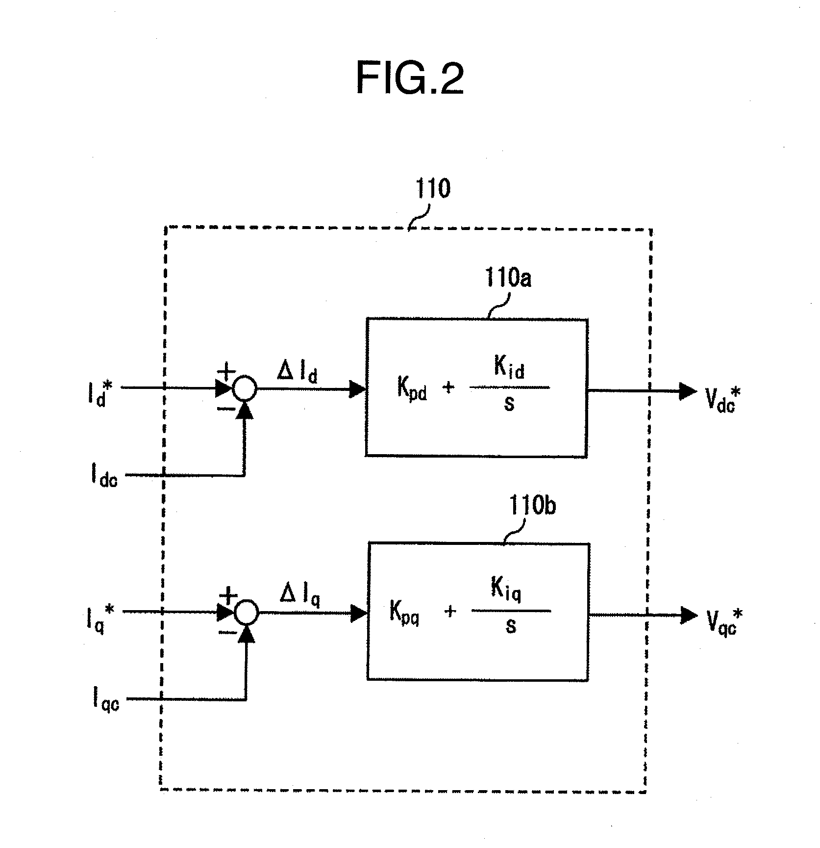
[0113]FIG. 11 illustrates another embodiment of the present invention.

[0114]In the first embodiment, a method using formula calculation is employed in the torque ripple suppression calculation section 113, however, in this embodiment, the torque ripple suppression calculation is performed using feedback compensation.

[0115]In this diagram, unless otherwise stated, the individual constituent element is the same as that of FIG. 1.

[0116]Next, a motor torque estimation calculation section 112 and torque ripple suppression calculation section 113 which are the features of the present invention are described.

[0117]The motor torque estimation calculation section 112 receives Vdc*, Vqc* which are the output values of the current control calculation section 110 and Idc, Iqc which are the output values of the coordinate conversion section 106, and outputs a torque estimation value τ̂ of the magnet motor 101.

[0118]The torque ripple suppression calculation section 113 receives the torque command...


PUM


Abstract

A sinusoidal signal is superimposed on a current command value of a q-axis (torque shaft) supplied from a host, and according to the resulting current command value, the output voltage of a power converter is controlled. For the calculation of the superimposed signal added to the current command value of the q-axis, with the use of the ripple component information of induced voltage coefficients of the d-axis and q-axis of the rotating coordinate system of a permanent magnet motor, the current command values of the d-axis and q-axis, an average value of induced voltage coefficients of the d-axis, and inductance values of the d-axis and q-axis, the sinusoidal superimposed signal is calculated and added to the above-described current command value of the q-axis.

Description

BACKGROUND OF THE INVENTION[0001]The present invention relates to a torque control apparatus for a permanent magnet motor, and in particular relates to the control apparatus for a permanent magnet motor capable of suppressing a torque ripple when there is a reluctance torque and there is an induced voltage distortion in an induced voltage waveform and thereby realizing an accurate torque control.[0002]As the method of suppressing a torque ripple when the induced voltage of a magnet motor has a square waveform (the induced voltage distortion), there is known a method comprising the steps of converting a three-phase induced voltage waveform into a voltage ed of a d-axis and a voltage eq of a q-axis and calculating a current command value Iqref of the q-axis (canceling the torque ripple) according to Formula (1), as in the description of JPA-2004-201487.Iqref=23(Tref×ωmeq)(1)Where[0003]Tref: a torque command value, andωm: the mechanical angle velocity of a motor.[0004]That is, even if ...

Claims


Application Information

Patent Timeline
Patent Type & Authority Applications(United States)
IPC IPC(8): H02P6/10B62D5/04H02P6/06H02P6/08H02P6/28H02P21/00H02P21/05H02P21/14H02P21/22H02P23/04H02P23/14H02P27/04
CPCH02P21/06H02P21/0035H02P21/22
Inventor TOBARI, KAZUAKIYOSHIKAWA, RIKIOMOCHIZUKI, KATSUHIRO
Owner KOKUSAN DENKI CO LTD
Why Eureka
Try Eureka