
Multi-channel breast MRI radio frequency receiver coil

a radio frequency receiver coil and receiver coil technology, applied in the field of medical imaging systems, can solve the problems of not providing access to the breasts during imaging, reducing the snr, and increasing the noise volume, so as to increase the snr, reduce the scan time, and improve the spatial resolution image

Inactive Publication Date: 2011-10-06
THE BOARD OF TRUSTEES OF THE LELAND STANFORD JUNIOR UNIV +1
View PDF15 Cites 24 Cited by
  • Summary
  • Abstract
  • Description
  • Claims
  • Application Information

AI Technical Summary

Benefits of technology

[0009]The present invention provides a modular radio frequency (RF) receiver coil array for a magnetic resonance (MR) imaging system. The receiver coil array is modular in nature in that fitted coil formers and coil arrangements are selected based on the breast size of the patient to be imaged, such that the fitted coil formers and the coil arrangements are placed closer to the breast than in conventional coil systems. The receiver coil array thus provides breast imaging with increased SNR, reduced scan time, and / or higher spatial resolution images for patients of various breast sizes.

Problems solved by technology

Such commercially available breast coils are comprised of larger coil elements, which leads to a bigger noise volume, reducing the SNR.
Several commercially available “closed” coil designs also exist for breast imaging, where the coils are constructed to substantially surround the breast, thereby not providing access to the breasts during imaging.
However, such coil designs use a one-size-fits-all policy where the coils are over-sized so as to fit larger size breasts.
Such closed coils are inefficient for imaging small and medium breasts, as the breasts of a patient may be separated from the coils by a distance large enough to affect image quality, such as by reducing the SNR.
For both the existing open and closed breast coil designs, inefficiencies exist due to the design of the coil.
That is, limitations of the coil geometry in such coils regarding how closely the coils can be placed relative to the breasts of the patient lead to reduced SNR and capability of parallel image acceleration in only one dimension.
This leads to reduced image quality and increased scan time.

Method used


Image

  • Multi-channel breast MRI radio frequency receiver coil
  • Multi-channel breast MRI radio frequency receiver coil
  • Multi-channel breast MRI radio frequency receiver coil

Examples


Embodiment Construction

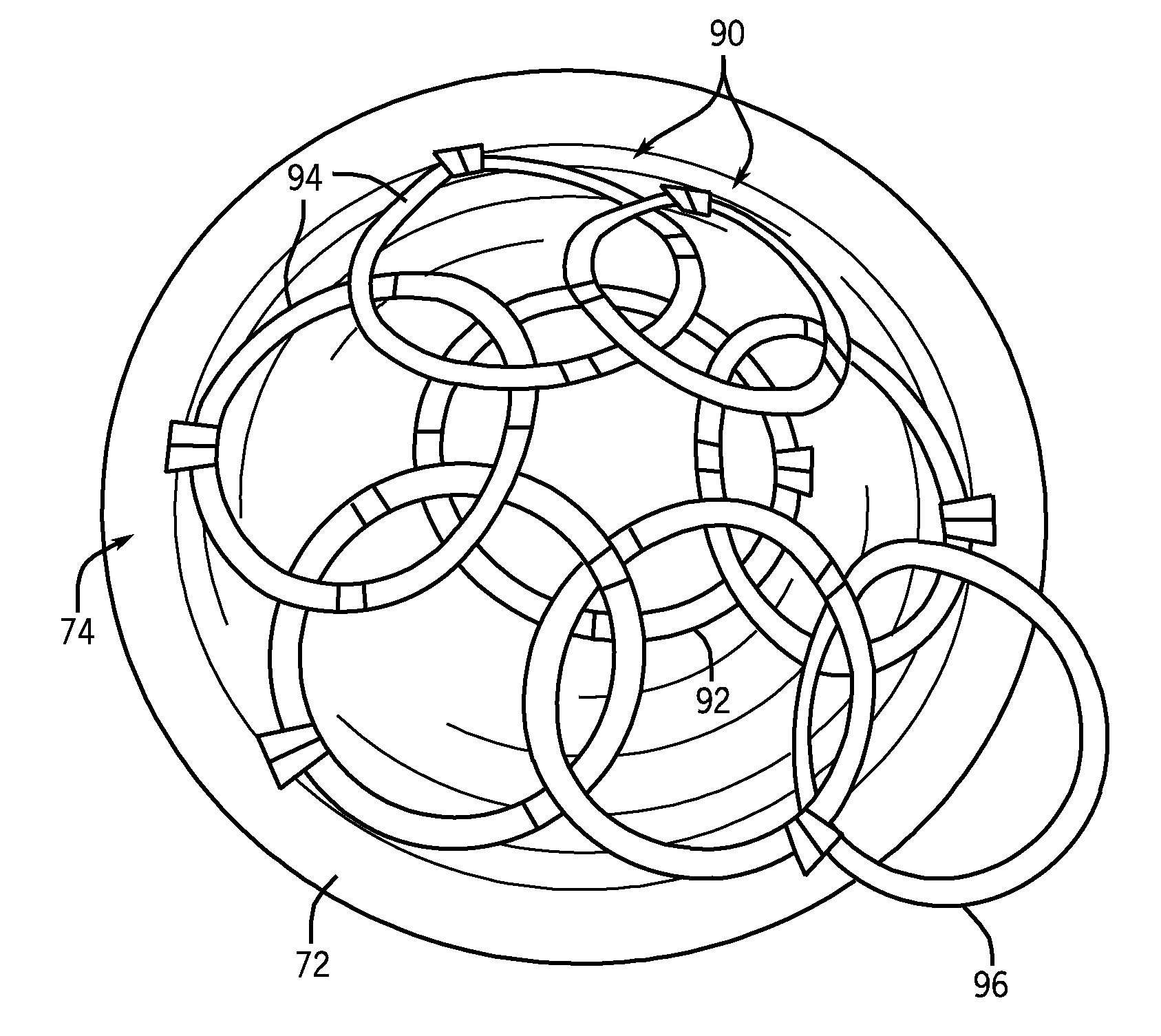
[0021]A modular RF receiver coil system is provided having a fitted coil former and receiver coil array that are sized based on the breast size of a patient to be imaged. The fitted coil former and receiver coil array are thus placed closer to the breast than conventional systems and conform closely thereto, so as to provide for increased signal-to-noise ratio (SNR) in acquired images as well as to maximize 2D parallel imaging acceleration in the superior / inferior and right / left directions.

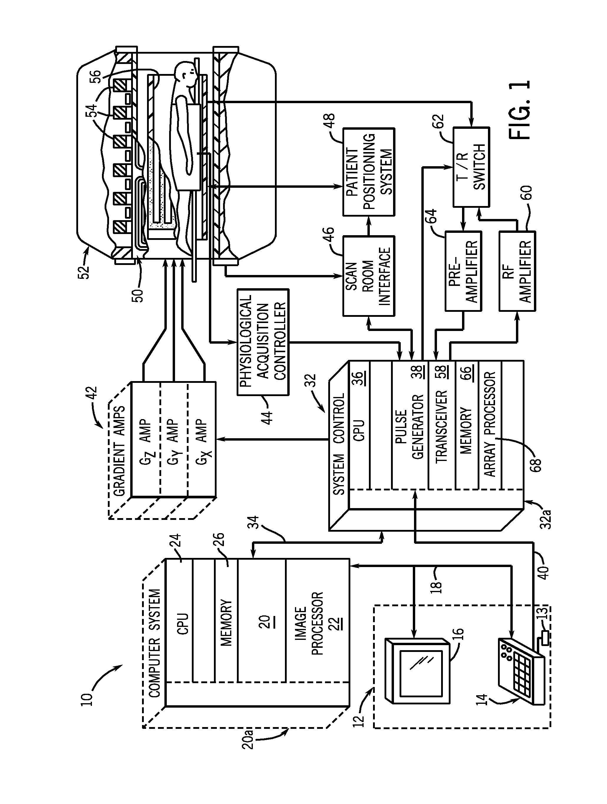
[0022]Referring to FIG. 1, the major components of a magnetic resonance imaging (MRI) system 10 incorporating an embodiment of the invention are shown. The operation of the system is controlled from an operator console 12 which includes a keyboard or other input device 13, a control panel 14, and a display screen 16. The console 12 communicates through a link 18 with a separate computer system 20 that enables an operator to control the production and display of images on the display screen 16. The...


PUM


Abstract

A system and method for breast imaging is disclosed. The system is constructed as a modular RF coil system for an MR imaging apparatus and includes a fitted coil former constructed to have a shape and size so as to substantially conform to a breast of a patient to be imaged and a receiver coil array positioned on the fitted coil former and having a plurality of receiver coils arranged to form a coil array. At least one of a size of each of the plurality of receiver coils and a number of the plurality of receiver coils is based on a size of the fitted coil former. Based on its coil arrangement and its proximity to the breasts of the patient to be imaged, the receiver coil array of the modular RF coil system is capable of receiving MR data for parallel imaging.

Description

GOVERNMENT LICENSE RIGHTS[0001]The present invention was made at least in part with Government support under Grant No. 1 R01 EB009055-01 and Grant No. P41 RR009784-11, each awarded by the National Institute of Health. The Government may have certain rights in the invention.BACKGROUND OF THE INVENTION[0002]The present invention relates generally to medical imaging systems and, more particularly, to a radio frequency (RF) receiver coil array for a magnetic resonance (MR) imaging system.[0003]When a substance such as human tissue is subjected to a uniform magnetic field (polarizing field B0), the individual magnetic moments of the spins in the tissue attempt to align with this polarizing field, but process about it in random order at their characteristic Larmor frequency. If the substance, or tissue, is subjected to a magnetic field (excitation field B1) which is in the x-y plane and which is oscillating at a radio frequency that is near the Larmor frequency, the net aligned moment, or...

Claims


Application Information

Patent Timeline
Patent Type & Authority Applications(United States)
IPC IPC(8): G01R33/44
CPCG01R33/5611G01R33/3415
Inventor NNEWIHE, ANDERSONHARGREAVES, BRIANDANIEL, BRUCE L.GRAFENDORFER, THOMASCALDERON, PAUL DAVIDROBB, FRASER JOHN LAING
Owner THE BOARD OF TRUSTEES OF THE LELAND STANFORD JUNIOR UNIV
Features
  • Generate Ideas
  • Intellectual Property
  • Life Sciences
  • Materials
  • Tech Scout
  • Unparalleled Data Quality
  • Higher Quality Content
  • 60% Fewer Hallucinations
Learn More