Headlamp assembly for motor vehicle

a technology for motor vehicles and headlamps, applied in indirect heat exchangers, lighting and heating apparatuses, transportation and packaging, etc., can solve the problems of short life, reduced light emission efficiency, and intrinsic drawbacks of light emitting diodes, so as to promote heat exchange and increase radiating performance , the effect of high efficiency

Inactive Publication Date: 2011-10-06
NIPPON SOKEN +1
View PDF1 Cites 6 Cited by
  • Summary
  • Abstract
  • Description
  • Claims
  • Application Information

AI Technical Summary

Benefits of technology

[0022]As previously described and will be explained in the following first to eighth embodiments, the headlamp assembly according to the present invention has a long air-flow path with which the heat exchange between the warmed air and the outside ambient air is executed with high efficiency. The heat exchange between the inner warmed air in the light chamber and the outside ambient air of the lens cover is also executed through the wall surface of the lamp cover. The structure of the headlamp assembly according to the present invention promotes the heat exchange and increases the radiating performance without increasing the entire size and electric power consumption of the headlamp assembly. The presence of the rib part and the sub-rib part further increases the radiating performance of the headlamp assembly.

Problems solved by technology

In general, a light emitting diode has an intrinsic drawback because of having a high heat density.
For example, when the temperature of a light emitting diode becomes increases, the light emitting efficiency is decreased, and its lifetime becomes short.
However, the conventional techniques previously described require an electric fan in a lamp chamber and / or a pump and a cooling pipe in order to forcedly cool the light emitting diodes.
This increases the entire size of the headlamp assembly, and electric power consumption because the conventional headlamp assemblies further need to have additional electric power in order to drive the above electric fan and pump.

Method used


Image

  • Headlamp assembly for motor vehicle
  • Headlamp assembly for motor vehicle
  • Headlamp assembly for motor vehicle

Examples


first embodiment

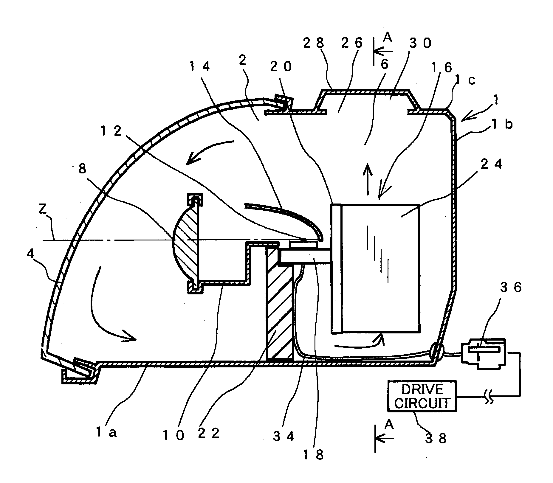
[0040]A description will be given of the headlamp assembly according to a first embodiment of the present invention with reference to FIG. 1 and FIG. 2.

[0041]FIG. 1 is a schematic view showing a vertical cross section of the headlamp assembly mounted to a vehicle according to the first embodiment of the present invention. As shown in FIG. 1, the headlamp assembly according to the first embodiment is comprised of a housing case 1, a front lens cover 4 and other various types of components. A front part 2 of the housing case 1 is open. The front lens cover 4 is fitted and fixed to the front part 2 of the housing case 1 in order to approximately close the inside of the housing case 1. That is, the housing case 1 and the front lens cover 4 makes a light chamber 6. The light chamber 6 accommodates the various types of components.

[0042]In the light chamber 6, a projection lens 8, a shade 10 and a light source 12 are arranged in turn along the optical axis Z of the light source 12 when obs...

second embodiment

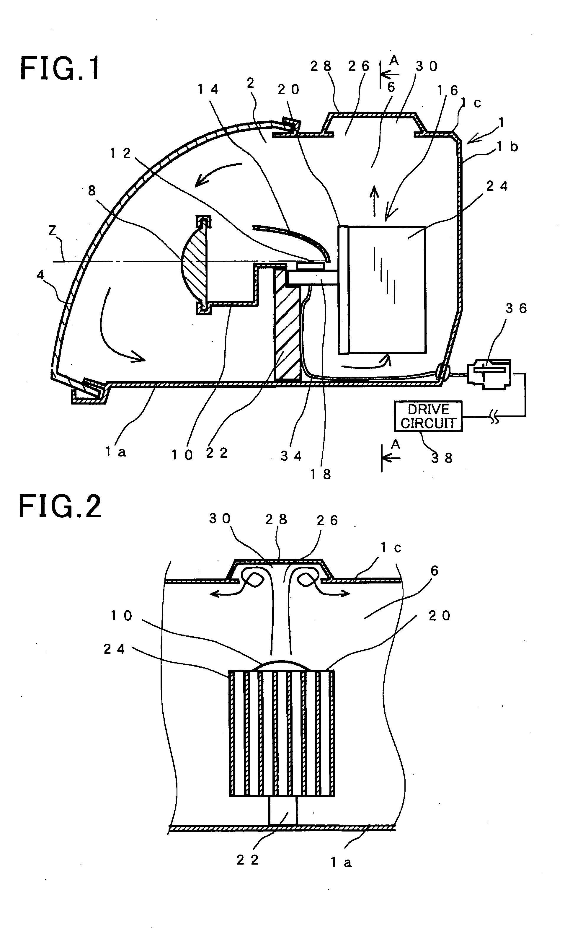
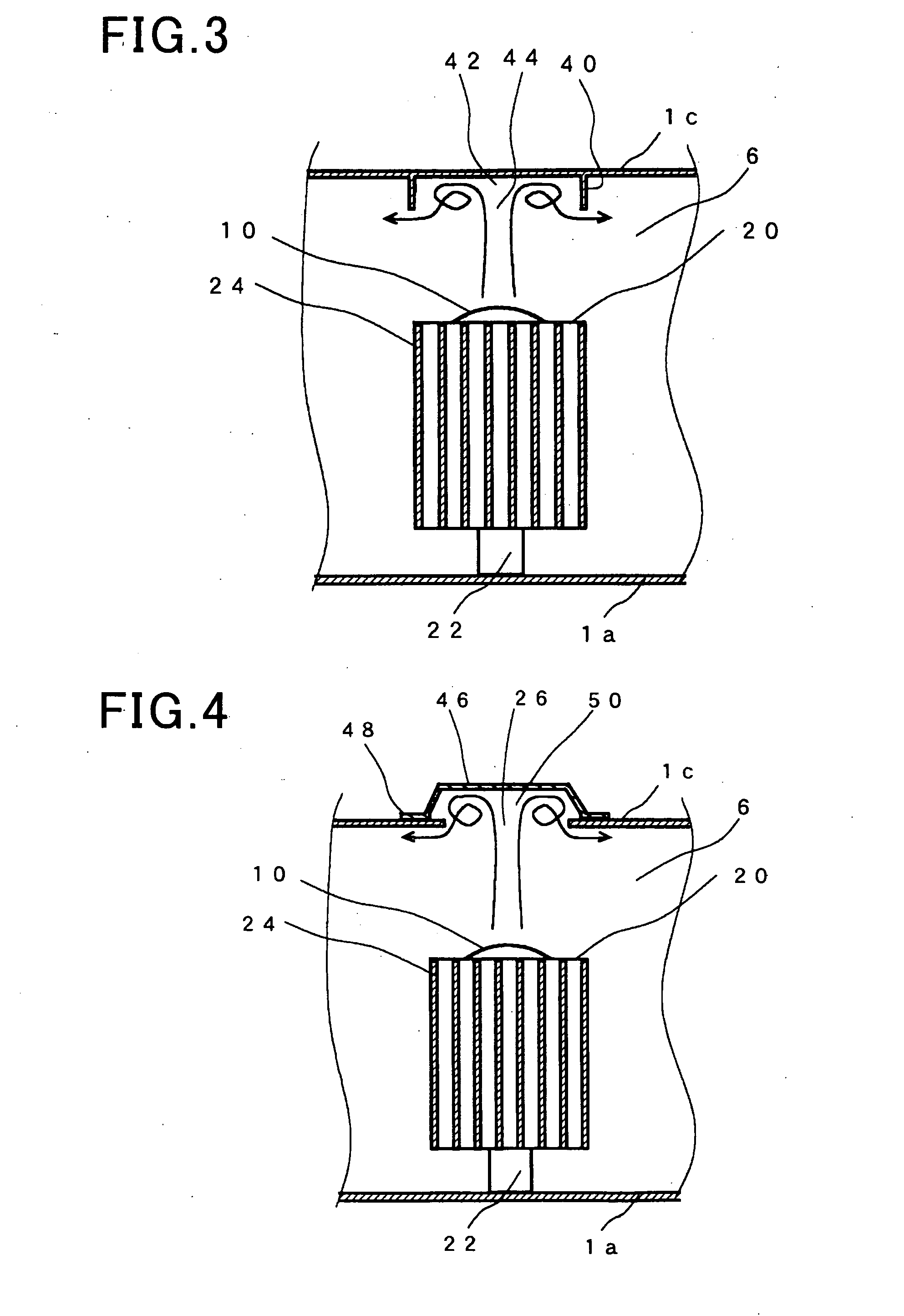
[0081]A description will be given of the headlamp assembly according to a second embodiment of the present invention with reference to FIG. 3.

[0082]FIG. 3 is a view showing a cross section of the headlamp assembly mounted to a vehicle according to the second embodiment of the present invention. The cross section shown in FIG. 3 corresponds to the cross section shown in FIG. 2 which shows the view along the A-A line shown in FIG. 1. The same components of the headlamp assemblies according to the first and second embodiments shown in FIG. 1 to FIG. 3 will be referred with the same reference numbers and the explanation of them is omitted for brevity.

[0083]In the headlamp assembly according to the second embodiment, a rib part 40 is formed on the ceiling wall 1c of the housing case 1. The rib part 40 vertically projects toward the radiating fins 24 from the ceiling wall 1c with a predetermined height. The ceiling wall 1c of the housing case 1 and the rib part 40 are assembled in one bod...

third embodiment

[0088]A description will be given of the headlamp assembly according to a third embodiment of the present invention with reference to FIG. 4.

[0089]FIG. 4 is a view showing a cross section of the headlamp assembly mounted to a vehicle according to the third embodiment of the present invention. The cross section shown in FIG. 4 corresponds to the cross section shown in FIG. 2 which shows the view along the A-A line shown in FIG. 1. The same components of the headlamp assemblies according to the first and second embodiments shown in FIG. 1 to FIG. 4 will be referred with the same reference numbers and the explanation of them is omitted for brevity.

[0090]In the structure of the headlamp assembly according to the third embodiment, the ceiling hole 26 is formed in the ceiling wall 1c of the housing case 1. The ceiling hole 26 is covered with a cover unit 46. The cover unit 46 is a member which is not integrally formed with the housing case 1. The cover unit 46 has a flange part 48 of a ri...


PUM


Abstract

In a light chamber formed by a housing case and a lens cover of a headlamp assembly, a projection lens and a light source are arranged in order along an optical axis of the light source from a front side of the light chamber. Radiating fins of a plate shape is vertically placed in the light chamber and radiate heat energy generated by the light source. A heat exchange chamber is formed in a ceiling wall of the housing case above the radiating fins. The heat exchange chamber has a concave shape from the ceiling wall of the housing case, and is open toward the radiating fins side.

Description

CROSS-REFERENCE TO RELATED APPLICATION[0001]This application is related to and claims priority from Japanese Patent Application No. 2010-082210 filed on Mar. 31, 2010, the contents of which are hereby incorporated by reference.BACKGROUND OF THE INVENTION[0002]1. Field of the Invention[0003]The present invention relates to headlamp assemblies for motor vehicles, equipped with one or more radiating members capable of radiating heat energy generated by one or more light sources.[0004]2. Description of the Related Art[0005]There are various types of headlamp assemblies mounted to motor vehicles equipped with light emitting diodes. For example, Japanese patent No. JP 4289268 has disclosed such a headlamp assembly comprised of a headlamp and a light emitting diode. In the headlamp assembly, a light projection lens, a shade and a light source are arranged in turn, and a reflector is arranged so that it faces the light source. The reflector reflects the light generated by the light source t...

Claims


Application Information

Patent Timeline
Patent Type & Authority Applications(United States)
IPC IPC(8): B60Q1/04
CPCF21S48/1159F21S48/328F21S48/321F21S45/49F21S45/60F21S45/48F21S41/148
Inventor TOMINAGA, MOTONORINISHII, TAKAHITOHORII, YASUTOSHI
Owner NIPPON SOKEN
Why Eureka
Try Eureka