Sliding bearing for internal combustion engines

a technology for internal combustion engines and sliding bearings, which is applied in the direction of bearings, rotary bearings, shafts and bearings, etc., can solve the problems of reducing the lubricity of the mating semi-cylindrical bearing, and affecting the lubrication of the bearing. , to achieve the effect of maximizing the blocking effect, good lubrication, and wide groove bottom width

Active Publication Date: 2011-10-06
DAIDO METAL CO LTD
View PDF6 Cites 9 Cited by
  • Summary
  • Abstract
  • Description
  • Claims
  • Application Information

AI Technical Summary

Benefits of technology

[0021](2) Lubricant oil mainly flowing through the circumferential oil groove during rotation of the crankshaft relative to the sliding bearing is accompanied by foreign substances. Foreign substances having a larger specific gravity than the lubricant oil move along the groove bottom by the action of a centrifugal force while the foreign substances are moving inside the circumferential oil groove. Thus, lubricant oil flowing through an upper region of the circumferential oil groove (i.e. the upper region closer to the crankshaft, not a lower region closer to the groove bottom) has a small amount of foreign substances. The lubricant oil with a small amount of foreign substances flowing through the upper region of the circumferential oil groove smoothly flows into the circumferential local groove in fluid communication with the circumferential oil groove, and spreads over the inner circumferential surface of the other side semi-cylindrical bearing having the circumferential local groove, which surface is brought into sliding contact with the crankshaft. Accordingly, good lubricity is obtained at the other side semi-cylindrical bearing. The above description applies to a case in which the groove depth (D1) of the circumferential oil groove and the groove depth (D2) of the circumferential local groove satisfy the relationship of D1>D2. In a case of D1≦D2, the foreign substances mo

Problems solved by technology

In a recent internal combustion engine, however, since a crankshaft is caused to rotate at a higher speed as a trend, and an inertia (under which the foreign substances are caused to move ahead) applied to the foreign substances becomes greater, the foreign substances are not discharged through clearances existing in circumferential end regions of the pair of semi-cylindrical bearings but move to a sliding surface zone of the other sliding bearing (i.e. the other semi-cylindrical bearing) having no circumferential oil groove, so that the sliding surface of the sliding bearing is liable to suffer damages due to the foreign substances.
Studying such sliding bearings in viewpoint of the foreign substances, there is a problem that a flow rate of the lubrica

Method used


Image

  • Sliding bearing for internal combustion engines
  • Sliding bearing for internal combustion engines
  • Sliding bearing for internal combustion engines

Examples


embodiment 1

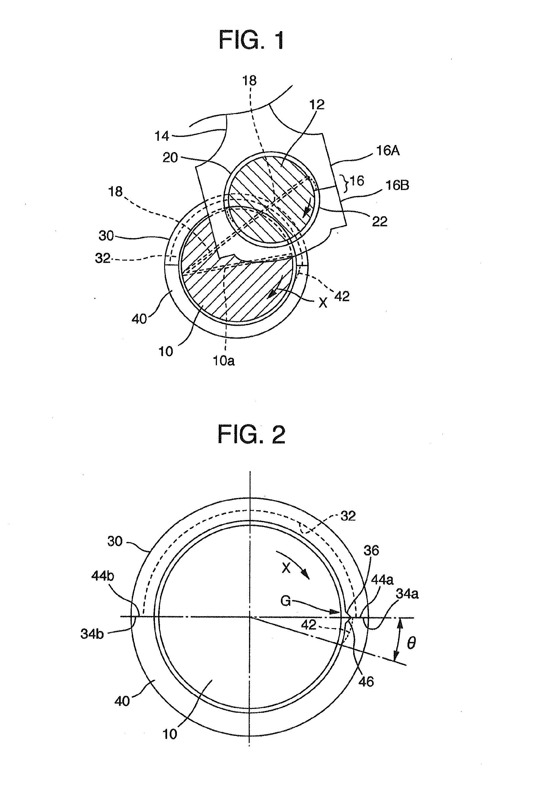
[0039]FIG. 1 is a schematic view illustrating a crankshaft of an internal combustion engine respectively cut along a journal portion and a crankpin portion. A crank journal 10, a crankpin 12, and a connecting rod 14 are shown therein. The three members are in such a positional relationship in the depth direction of the figure that the journal 10 is farthest from the front, and the crankpin 12 is on the near side and is surrounded by a big end housing 16 of the connecting rod 14 that carries a piston on the other end.

[0040]The crank journal 10 is supported on a lower portion of a cylinder block of the internal combustion engine via a cylindrical sliding bearing including an upper semi-cylindrical bearing 30 and a lower semi-cylindrical bearing 40. A circumferential oil groove 32 is formed over the entire length of an inner circumferential surface of the upper semi-cylindrical bearing 30 located on the upper side of the drawing.

[0041]The crank journal 10 also has a diametrical through...

embodiment 2

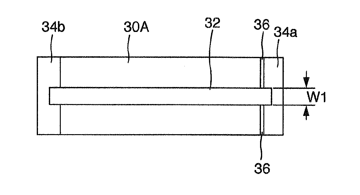
[0056]A second embodiment shown in FIGS. 8 to 10 will be described. The second embodiment has the same configuration as the first embodiment except for some portions. Only differences therebetween will be described below.

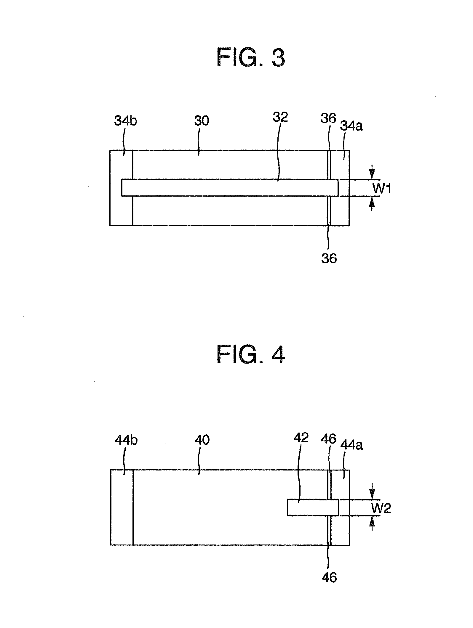
[0057]The groove width (W1) of the circumferential oil groove 32 (a groove of an upper semi-cylindrical bearing 30A) and the groove width (W2) of the circumferential local groove 42 (a groove of a lower semi-cylindrical bearing 40A) satisfy a relational expression: W21.

[0058]A preferable relationship between W1 and W2 is 0.50×W121.

[0059]The relationship of W21 means that a region of 5% or more of the groove width from both the inner sides of the circumferential oil groove 32 and adjacent to the groove bottom is preferably blocked by the circumferential end 44a.

[0060]The relationship of 0.50×W12 is required for ensuring a flow passage sectional area to supply a sufficient amount of lubricant oil from the circumferential oil groove 32 to the circumferential local gro...

embodiment 3

[0063]A sliding bearing shown in FIGS. 11 to 13 includes an upper semi-cylindrical bearing 30B and the lower semi-cylindrical bearing 40. The lower semi-cylindrical bearing 40 is the same as the lower semi-cylindrical bearing 40 in the first embodiment. The upper semi-cylindrical bearing 30B differs from the upper semi-cylindrical bearing 30 in the first embodiment in the following point. An open groove end of a circumferential oil groove 32B is provided only at the circumferential end 34a. That is, the circumferential oil groove 32B extends from the circumferential end 34a to a position close to the circumferential end 34b, so that the open groove end is not provided at the circumferential end 34b. The sum (=a circumferential angle θ2) of a circumferential range in which the circumferential oil groove 32B of the upper semi-cylindrical bearing 30B is formed and a circumferential range in which the circumferential local groove 42 of the lower semi-cylindrical bearing 40 is formed is ...


PUM


Abstract

Disclosed is a sliding bearing for supporting a crankshaft journal portion of an internal combustion engine. One of the semi-cylindrical bearings is provided with a circumferential oil groove on its inner circumferential surface, and has two circumferential ends. The circumferential oil groove has an open groove end at at least one of the two circumferential ends, which one is a first circumferential end being directed to the same direction as a relative rotational direction of a crankshaft. The other semi-cylindrical bearing is provided with at least one circumferential local groove on its inner circumferential surface, and has two circumferential ends. The circumferential local groove has an open groove end at one of the two circumferential ends, which one is a second circumferential end being directed to the opposite direction to the relative rotational direction of the crankshaft. The circumferential oil groove and the local circumferential groove are in fluid communication with each other. At a region of the fluid communication, a groove bottom of the local circumferential groove is deviated toward an axis of the sliding bearing from another groove bottom of the circumferential oil groove. An axial groove is formed along a contact interface between the first and second circumferential ends.

Description

CROSS-REFERENCE TO RELATED APPLICATIONS[0001]The present application claims priority from JP Patent Application Ser. No. JP-2010-82418 filed on Mar. 31, 2010, the content of which is hereby incorporated by reference into this application.TECHNICAL FIELD[0002]The present invention relates to a sliding bearing for supporting a crankshaft journal portion of an internal combustion engine, which is a cylindrical body formed from a combination of a pair of semi-cylindrical bearings.BACKGROUND ART[0003]A conventional sliding bearing for supporting a crankshaft journal portion has been used as a cylindrical body formed by combining two semi-cylindrical bearings. In the sliding bearing, a circumferential oil groove is formed on an inner circumferential surface of at least one of the pair of semi-cylindrical bearings, through which circumferential oil groove oil is fed to an outer circumferential surface of a crankpin. In general, the circumferential oil groove has been made to have a constan...

Claims


Application Information

Patent Timeline
IPC IPC(8): F16C33/10
CPCF16C9/02F16C17/022F16C33/1065F16C33/105F16C33/046F16C33/10F16C17/02
Inventor UKAI, TOMOHIROISHIGO, OSAMUOZAWA, YOSHIHIRO
Owner DAIDO METAL CO LTD
Why Eureka
Try Eureka