Pulsed magnetic actuation for sensitive assays

a magnetic actuator and sensitive technology, applied in the field of magnetic field control, can solve the problems of signal loss, decreased sensitivity of assay, and very laborious and time-consuming methods, and achieve the effect of reducing sensitivity and avoiding surface damag

Active Publication Date: 2011-10-06
SIEMENS HEALTHINEERS NEDERLAND BV
View PDF7 Cites 9 Cited by
  • Summary
  • Abstract
  • Description
  • Claims
  • Application Information

AI Technical Summary

Benefits of technology

[0017]There is therefore a need to provide a system and a method which avoids the above discussed decrease of sensitivity. In particular, there is a need for a system and a method which minimizes the above described undesired removal or accumu

Problems solved by technology

Such a method is very laborious and time-consuming and needs a complex support system for arranging the two magnets on opposite sides of the sensor cartridge.
If these forces are too large and one bond is broken, the signal is lost and the sensitivity of the assay decreases.
In other words, in biosensors using actuated magnetic particles, the bonds that keep a particle bound to the sensor surface can be disrupted again as a result of too harsh actuation.
During actuation, however, the forces that are exerted on the particles can be too large to keep the particles bound to the surface, which finally results in a lower signal.
Especially the non-covalent bonds are susceptible to disruption if enough force is exerted on the particle.
It has been found that the disruption of the bond(s) is often irreversible, resulting in less functionality of the particle or the sensor surface, ultimately leading to a decreased sensitivity of the assay.
Therefore, this problem arises in particular in as

Method used


Image

  • Pulsed magnetic actuation for sensitive assays
  • Pulsed magnetic actuation for sensitive assays
  • Pulsed magnetic actuation for sensitive assays

Examples


Embodiment Construction

[0059]The inventors of the present invention identified the presence of lateral forces (parallel to the sensor surface), acting on particles that are close to the sensor surface as one of the main contributors of the above described problem. Compared to forces perpendicular to the sensor surface, these lateral forces can probably induce much higher forces on the biological bonds through the large torque that is created.

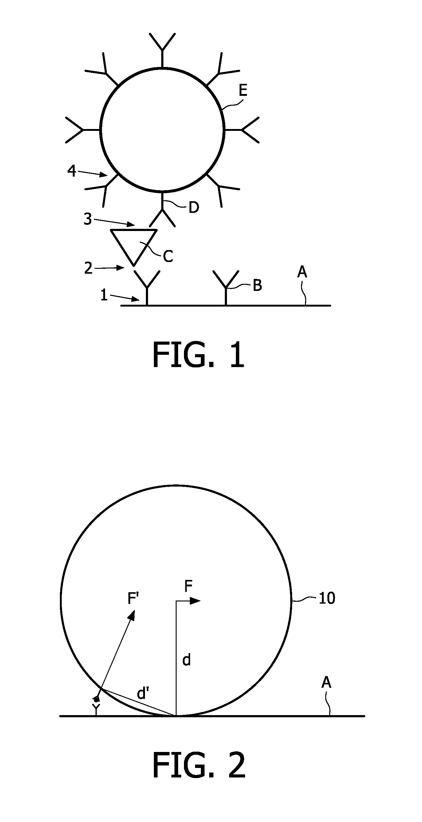
[0060]In particular, FIG. 2 illustrates how a relatively small force F, parallel (lateral) to the sensor surface, can induce a relatively larger force on a biological bond due to the long arm “d” created by the relatively large size of the magnetic particle 10. The resulting force, which acts on the bond between the particle and the bond is indicated by F′ which is significantly larger than the parallel force F. Moreover, the inventors of the present invention also observed that single unbound particles can be dragged over the sensor surface and remove already bound p...


PUM


Abstract

A method for controlling the movement of magnetic or magnetizable objects (10) in a biosensor cartridge. The method comprises the step of providing a biosensor cartridge with a laterally extending sensor surface (A) and at least a magnetic field generating means (20, 30, 30′) for generating a magnetic field with a field gradient substantially perpendicular to the sensor surface (A). The magnetic field generating means (20, 30, 30′) are alternatingly actuated such that the generated magnetic field directs alternatingly the magnetic or magnetizable objects (10) substantially perpendicular to the sensor surface (A) away and toward the sensor surface, wherein pulse lengths of the alternating actuation are adjusted such that a lateral movement of magnetizable objects along the laterally extending sensor surface is substantially avoided.

Description

FIELD OF THE INVENTION[0001]The present invention relates to method for controlling the magnetic field for a pulsed magnetic actuation and for detection of magnetic or magnetizable objects in a biosensor system. The present invention also relates to a biosensor system with at least two magnetic field generating means for the pulsed actuation of magnetic particles in a biosensor systems, the controlled movement of magnetic or magnetizable objects and the detection of magnetic or magnetizable objects in a cartridge of a biosensor system.BACKGROUND OF THE INVENTION[0002]Various analytical procedures to detect an analyte in a test sample are known. For example, immunoassays use the mechanisms of the immune system, wherein antibodies and the respective antigens are capable of binding to one another. This specific reaction mechanism is used to determine the presence or concentration of the antigen in a test sample. In particular, the antibody or the antigen (analyte of interest) is labele...

Claims


Application Information

Patent Timeline
IPC IPC(8): G01N33/543G01N27/72
CPCB01L3/502761B01L2200/0668B01L2400/043B03C1/288G01R33/1269B03C2201/18G01N27/745G01N33/54333B03C5/028B03C2201/26G01N35/0098
Inventor EVERS, TOON HENDRIKOVSYANKO, MIKHAIL MIKHAYLOVICH
Owner SIEMENS HEALTHINEERS NEDERLAND BV
Why Eureka
Try Eureka