Electric outboard motor

a technology of electric motors and outboard motors, applied in the direction of propulsive elements, marine propulsion, vessel construction, etc., can solve the problems of adversely affecting the electric motor, complicated structure, and heat generation, and achieve the effect of improving the cooling efficiency of the electric motor

Inactive Publication Date: 2011-10-06
SUZUKI MOTOR CORP
View PDF5 Cites 0 Cited by
  • Summary
  • Abstract
  • Description
  • Claims
  • Application Information

AI Technical Summary

Benefits of technology

[0011]The present invention has been made in view of problems as described above, and has an object to improve cooling efficiency of an electric motor to be used in an electric outboard motor.

Problems solved by technology

However, in the above-described electric outboard motors, the electric motor is covered with the motor cover to thereby cause a problem that heat to be generated when the electric motor is driven is confined in the motor cover.
A temperature in the motor cover increases to thereby adversely affect the electric motor, the control unit, and so on that are housed in the motor cover.
Thus, not only the number of components of the electric outboard motor is increased to make the structure complicated, but also the weight of the electric outboard motor is increased and the motor cover is increased in size in order to house a cooling device therein, thereby causing a fear that maneuverability of the electric outboard motor is impaired.
On the other hand, even though the motor cover is simply removed to increase cooling efficiency, there is a fear that the electric motor and the control unit are exposed to the water, resulting that a function of the electric outboard motor itself deteriorates.

Method used


Image

  • Electric outboard motor
  • Electric outboard motor
  • Electric outboard motor

Examples


first embodiment

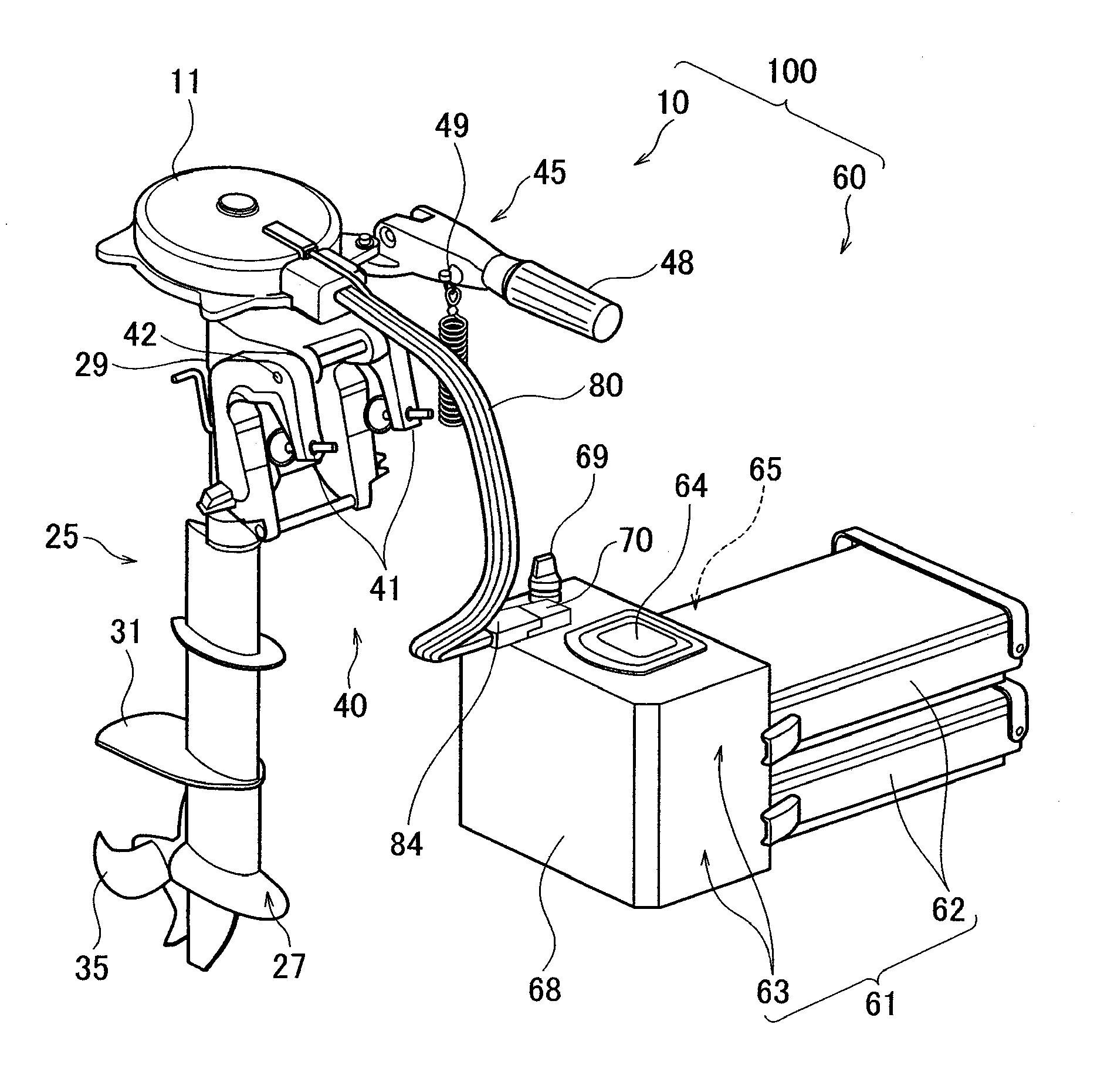
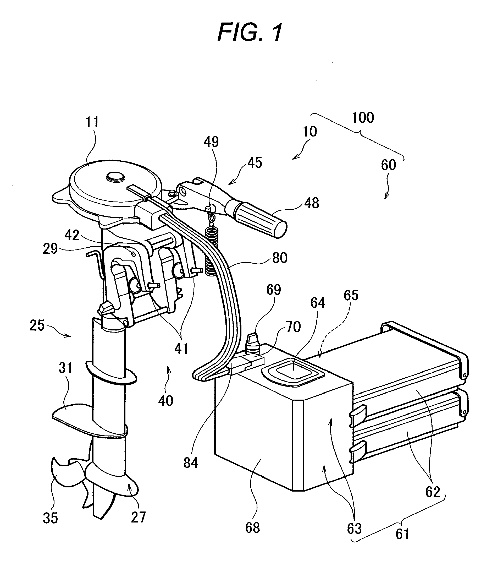
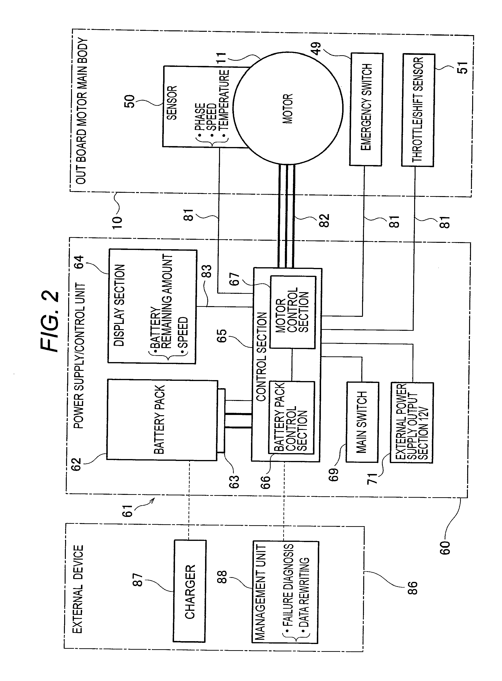
[0040]The entire structure of an electric outboard motor 100 according to an embodiment will be explained with reference to FIG. 1 and FIG. 2. FIG. 1 is an appearance view of the electric outboard motor according to this embodiment, and FIG. 2 is a view showing an electric outboard motor system including the electric outboard motor.

[0041]As shown in FIG. 1, the electric outboard motor 100 is provided with an electric outboard motor main body 10 and a power supply / control unit 60, and the both are formed separately. Further, the electric outboard motor main body 10 and the power supply / control unit 60 are electrically connected by a cable 80. The electric outboard motor main body 10 and the power supply / control unit 60 are formed separately, thereby separating the power supply / control unit 60 from the electric outboard motor main body 10 to enable the power supply / control unit 60 to be disposed at a position where a barycenter balance in a hull is stabilized, resulting that it is pos...


PUM


Abstract

In an electric outboard motor to be driven by an electric motor, the electric motor is formed in a watertight manner and is disposed to be exposed to the outside. Further, the electric motor is an air cooled type, and a shape of the electric motor is in a substantially flat shape in which a dimension in a horizontal direction perpendicular to an output shaft of the electric motor is made larger than a dimension in a height direction. The electric motor, when a hull is seen in plan view, is disposed in a manner that a front portion of the electric motor overlaps a transom board of the hull at the rear.

Description

CROSS-REFERENCE TO RELATED APPLICATIONS [0001]This application is based upon and claims the benefit of priority of the prior Japanese Patent Application No. 2010-083232, filed on Mar. 31, 2010, the entire contents of which are incorporated herein by reference.BACKGROUND OF THE INVENTION [0002]1. Field of the Invention[0003]The present invention relates to an electric outboard motor.[0004]2. Description of the Related Art[0005]In recent years, in consideration of an influence on an environment, an electric outboard motor to be driven by an electric motor has been attracting attention. For example, in Patent Document 1 and Patent Document 2, there has been disclosed an electric outboard motor having an electric motor housed in a motor room of an outboard motor main body. These electric outboard motors each have a structure such that output of the electric motor, namely rotation of an output shaft is transmitted to a propeller shaft through a drive shaft and a bevel gear to rotate a pr...

Claims


Application Information

Patent Timeline
Patent Type & Authority Applications(United States)
IPC IPC(8): B63H21/17
CPCB63H21/17B63H20/007
Inventor DAIKOKU, KEISUKEACHIWA, TETSUSHIKIMPARA, MASATOSHI
Owner SUZUKI MOTOR CORP
Why Eureka
Try Eureka