Ultrasound diagnostic apparatus

a technology of ultrasound and diagnostic equipment, applied in tomography, applications, instruments, etc., can solve the problems of reducing the maneuverability of ultrasound probes, mixing external noise and attenuation, and reducing so as to achieve high precision and reduce the thickness and weight of connection cables

Inactive Publication Date: 2011-10-06
FUJIFILM CORP
View PDF4 Cites 14 Cited by
  • Summary
  • Abstract
  • Description
  • Claims
  • Application Information

AI Technical Summary

Benefits of technology

[0010]The present invention was developed to resolve these problems of the past, and its objective is to provide an ultrasound diagnostic apparatus which reduces the thickness and weight of the connection cable which connects the ultrasound probe and apparatus body, while being able to detect reception signals with high precision.

Problems solved by technology

When the number of signal wires increases, problems occur in that the connection cable becomes thick and heavy, and maneuverability of the ultrasound probe decreases.
If each signal wire of the connection cable is made lighter and narrower in order to counteract these problems, it causes problems in that mixing in of external noise and attenuation due to the resistance of the signal wires occur, and detection precision of the reception signal is markedly reduced.
However, in the ultrasound diagnostic apparatus according to JP 2005-279130 A, a certain delay is provided to both the high-voltage drive signals for driving the ultrasound transducers and to the tiny reception signals, but in general, the time precision of analog delay wires is low, and it is difficult to delay drive signals which are more than 100 V at maximum with high precision.
Also, realizing the apparatus disclosed in JP 2007-209700 A is difficult because a practical electronic switch that can operate at a high speed of about 1 μs while having a breakdown voltage of 100 V or above has not yet been developed.

Method used


Image

  • Ultrasound diagnostic apparatus
  • Ultrasound diagnostic apparatus
  • Ultrasound diagnostic apparatus

Examples


embodiment 1

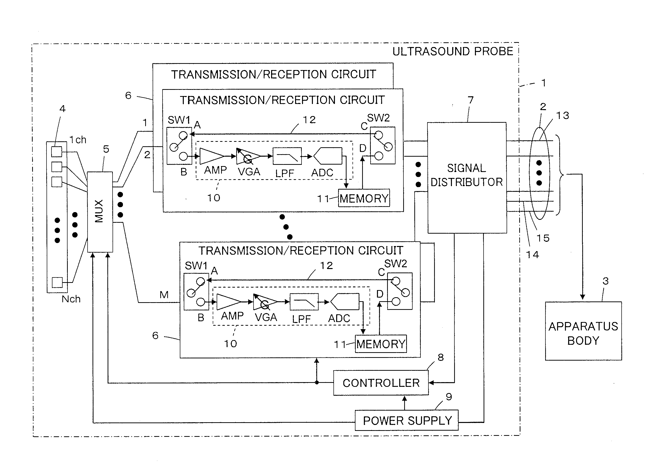
[0031]FIG. 1 illustrates a configuration of an ultrasound diagnostic apparatus according to embodiment 1 of the invention. The ultrasound diagnostic apparatus comprises an ultrasound probe 1, and an apparatus body 3 which is electrically connected to the ultrasound probe 1 via a connection cable 2.

[0032]The ultrasound probe 1 has N ultrasound transducers 4 of a 1st channel through an Nth channel arranged in an array. M transmission / reception circuits 6 are connected to these ultrasound transducers 4 via a multiplexer 5, and a signal distributor 7 is connected to these M transmission / reception circuits 6. Additionally, a controller 8 for controlling the operation of the multiplexer 5 and the transmission / reception circuits 6 is connected to the signal distributor 7, and a power supply 9 which supplies power to the multiplexer 5, the transmission / reception circuits 6 and the controller 8 is also connected to the signal distributor 7.

[0033]Each transmission / reception circuit 6 has a re...

embodiment 2

[0062]FIG. 4 illustrates the internal structure of an ultrasound probe used in an ultrasound diagnostic apparatus according to embodiment 2.

[0063]Here, m signal wires S1-Sm of the connection cable 2 are connected to N ultrasound transducers 4 of the 1st to Nth channels arranged in an array via a high-voltage multiplexer 41.

[0064]Also, a low-voltage multiplexer 43 is connected to the N ultrasound transducers 4 via respective overvoltage protection circuits 42, and M receiving circuits Rx1-RxM are connected to this low-voltage multiplexer 43. Each of the receiving circuits Rx1-RxM, similar to the receiving circuit 10 in embodiment 1 shown in FIG. 1, has a preamp AMP and a variable gain amp VGA which amplify a reception signal, a low pass filter LPF which removes high-frequency components not used in signal detection from the reception signal, and an A / D converter ADC which converts the reception signal to a digital signal, which are connected in series in that order.

[0065]A common mem...

embodiment 3

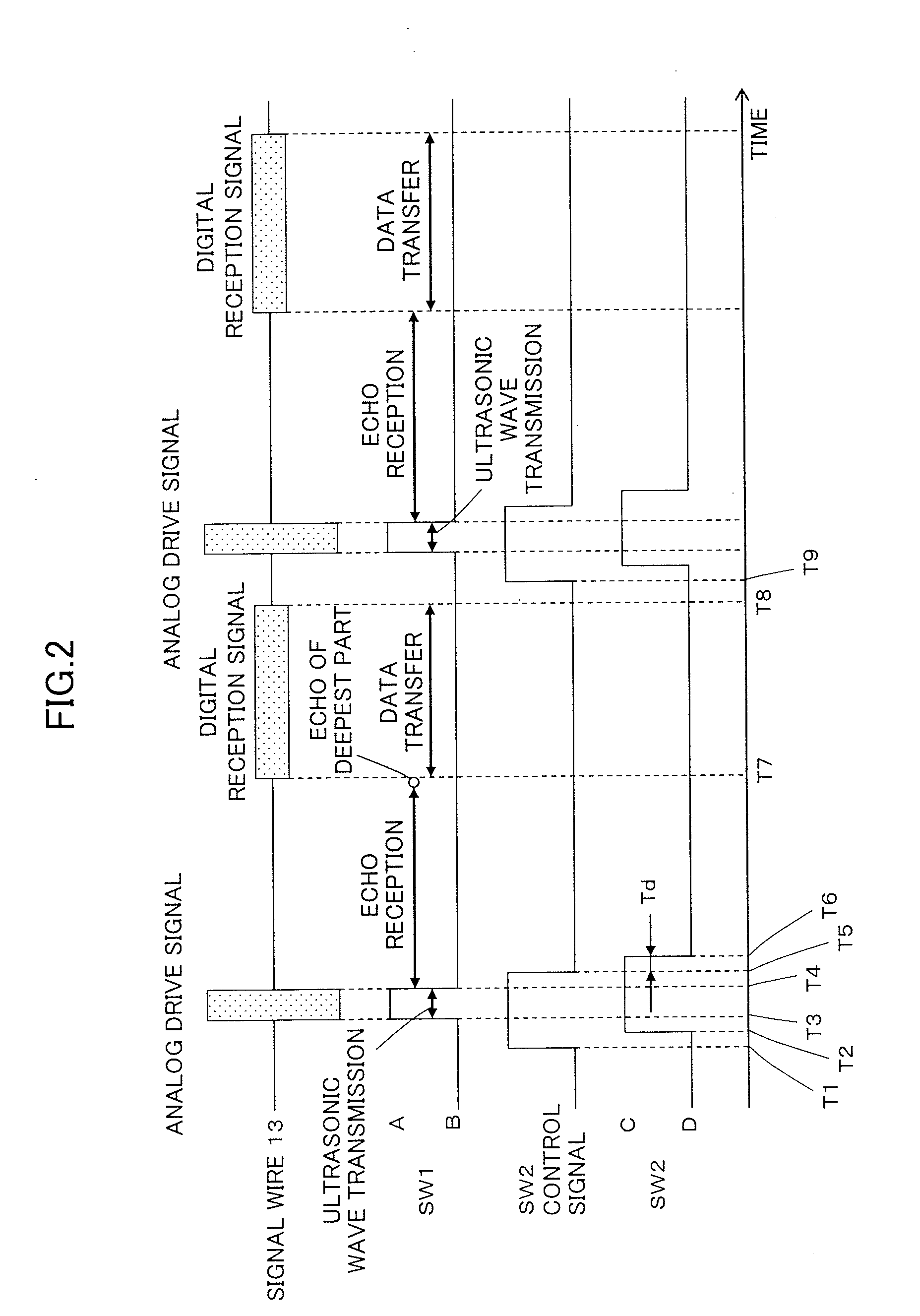
[0084]If a plurality of ultrasound transducers can be driven by one signal wire of the connection cable during one transmission period of ultrasonic waves, the number of signal wires in the connection cable can be reduced, and the weight of the connection cable can be reduced.

[0085]For example, as shown in FIG. 7, if an aperture width W of an ultrasound probe is 40 mm, a maximum transmission aperture width We is 20 mm, a transmission focal length Lf is 5-70 mm and the speed of sound c is taken as 1530 m / s, a delay time τ between a transmission aperture center O and a transmission aperture edge E when ultrasonic waves are transmitted from the ultrasound probe 1 in the forward direction is

τ=(Lef−Lf) / c

Here, Lef indicates the distance between the focal point F and the transmission aperture edge E. FIG. 8 graphically shows the delay time τ as a function of transmission focal length Lf. The delay time τ corresponding to transmission focal length Lf=5-70 is about 4 μs or less.

[0086]In con...


PUM


Abstract

An ultrasound diagnostic apparatus comprises: an ultrasound probe having a plurality of ultrasound transducers; an apparatus body which supplies analog drive signals to the ultrasound transducers and generates ultrasound images based on reception signals output from the ultrasound transducers; and a connection cable which connects the ultrasound probe and the apparatus body, the ultrasound probe comprising: a plurality of receiving circuits, each including a preamp which amplifies the reception signal output from one of the ultrasound transducers and an A / D converter which converts the amplified reception signal; and a time division unit which controls output of the reception signal to the apparatus body such that the drive signal supplied from the apparatus body and the reception signal output to the apparatus body after being converted to a digital signal by the receiving circuit are mutually time-divided and sent via the connection cable.

Description

BACKGROUND OF THE INVENTION[0001]The present invention relates to an ultrasound diagnostic apparatus, particularly to an ultrasound diagnostic apparatus which transmits an ultrasonic beam from an ultrasound probe toward a subject, receives ultrasonic echoes reflected by the subject by an ultrasound probe and sends that reception signal to an apparatus body, wherein the apparatus body and ultrasound probe are connected by a connection cable.[0002]In recent years, ultrasound diagnostic apparatus that use ultrasound images have been put to use in the medical field. In general, this type of ultrasound diagnostic apparatus has an ultrasound probe equipped with a plurality of ultrasound transducers arranged in an array, and an apparatus body connected to the ultrasound probe via a connection cable. It transmits ultrasonic waves from the ultrasound probe toward a subject, receives the ultrasonic echoes from the subject by the ultrasound probe, and generates an ultrasound image by digitally...

Claims


Application Information

Patent Timeline
Patent Type & Authority Applications(United States)
IPC IPC(8): A61B8/14
CPCA61B8/08A61B8/14A61B8/4461G01S15/8915G01S7/52079G01S7/5208G01S15/8927A61B8/54
Inventor SATO, TOMOO
Owner FUJIFILM CORP
Why Eureka
Try Eureka