Device for installing conducting components in structures

Active Publication Date: 2011-10-13
AIRBUS OPERATIONS SL
View PDF5 Cites 15 Cited by
  • Summary
  • Abstract
  • Description
  • Claims
  • Application Information

AI Technical Summary

Benefits of technology

[0011]This objective is achieved by means of a device which comprises an installation element onto which the conducting equipment or component is secured, a conducting insert element, through which the installation element is connected to the composite material structure through its internal part, a conducting layer, arranged on the external part of the installation element and a conducting fixing element which joins the composite material structure and the installation element, together with the insert element and the conducting layer. The configuration described of the abovementioned device manages to ensure, for the case of an atmos

Problems solved by technology

As is well known, these composite materials have very low or zero electrical conductivity, with these electrical properties being insufficient to protect the different, generally metallic, components or equipment installed on the aforementioned aeronautical structures made from composite material, in the case that any electrical discharge takes place to them.
In these cases, the composite material structures themselves are seriously damaged.
This solution, however, is not valid in the case that the aeronautical structure is made from composite material, given that it would not inherently provide a low impedance path for the electrical current from, for example, an electrical discharge to the structure, which would be capable of protecting both the metallic component or equipment and the composite material structure.
In the particular cases in which the composite material structures belong to parts of the aircraft at high risk from discharges, such as is the case for structures through which fuel for the aircraft passes, the direct installation of metallic components or equipment onto the composite material structure would provide a path for the electrical current with high electrical imped

Method used


Image

  • Device for installing conducting components in structures
  • Device for installing conducting components in structures

Examples


Example

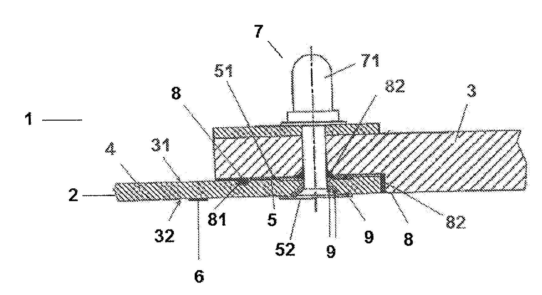
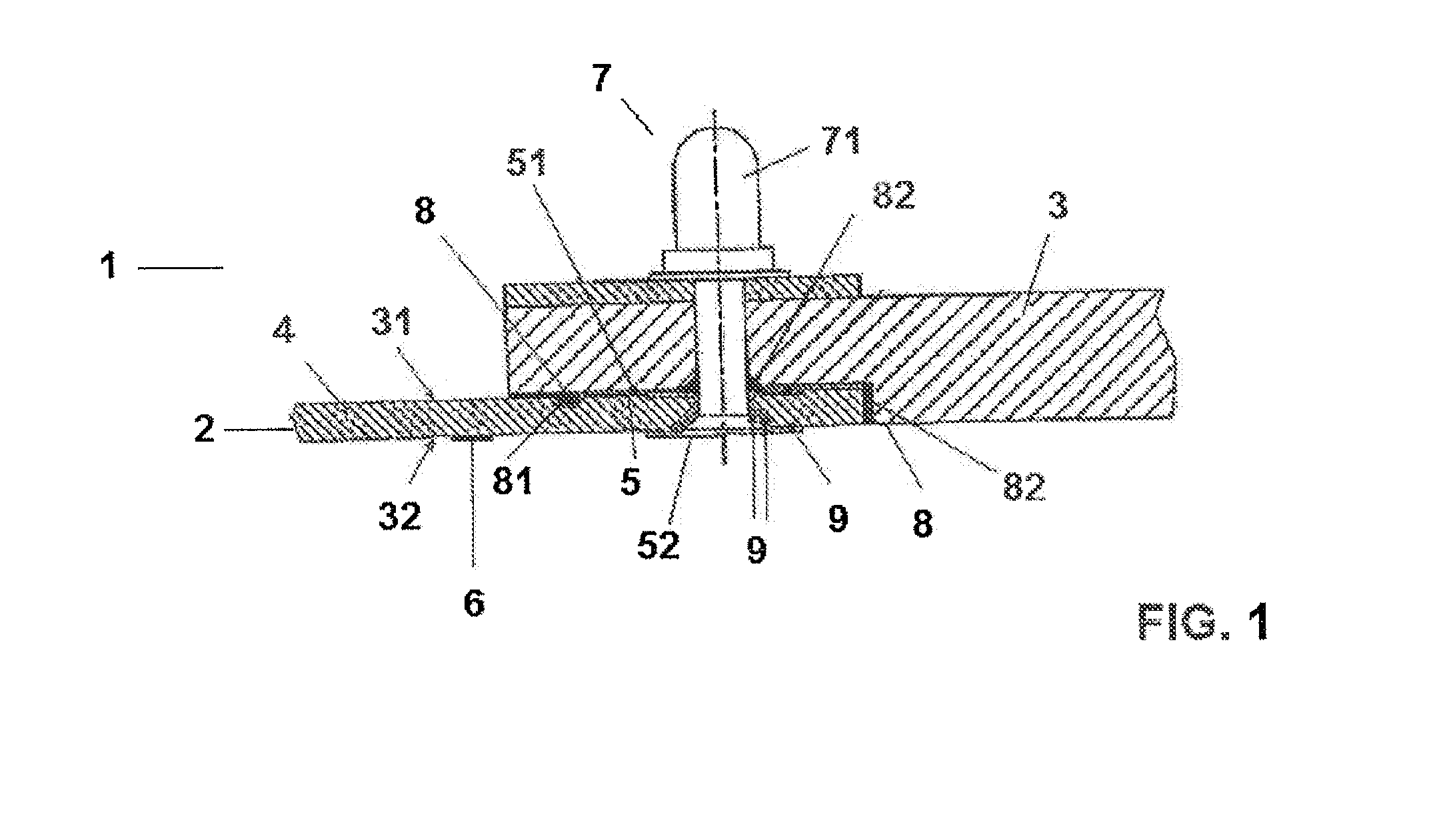
[0015]This invention refers to a device 1 for installing conducting components 2 or equipment, preferably made of metal, on structures 3, preferably aeronautic structures, of high electrical impedance, these structures 3 preferably being made of composite material. The interior of these structures 3 usually comprises highly flammable material, such as fuel. In general, these structures 3 belong to any element of a fuel tank which stores any gas or mixture of gases whose vapour can ignite at energies of 200 microjoules and up. This value, for the specific case of aeronautical structures, is given by the characteristics of the kerosene fuel used in aviation. The device 1 of the invention is capable of providing the component 2, which is connected to the structure 3 of the aircraft, with the electrical continuity necessary to prevent damage both to the structure 3 and the component 2 in the case of an electrical discharge. This discharge may come either from atmospheric discharges, for...


PUM

PropertyMeasurementUnit
Fractionaaaaaaaaaa
Electrical resistanceaaaaaaaaaa
Metallic bondaaaaaaaaaa

Abstract

A device (1) for the installation of a conducting component (2) on a structure (3) made from composite material, the inside of this structure (3) comprising a substance which can be ignited, which comprises an installation element (4) onto which the conducting component (2) is positioned, a conducting insert element (5), by means of which the installation element (4) is joined to the composite material structure (3) by its internal part, a conducting layer (6) arranged on the external part of the installation element (4) and a conducting fixing element (7) which joins the structure (3) and the installation element (4) to the insert element (5) and the conducting layer (6) so that the device (1) defines a low impedance current path through the conducting layer (6) and the insert element (5) through which the energy is dissipated from an atmospheric discharge to the component (2) or to the structure (3), the interior face of the structure (3) remaining isolated.

Description

FIELD OF THE INVENTION[0001]This invention refers to a device for installing conducting components in structures, in particular in aeronautical structures made from composite material.BACKGROUND OF THE INVENTION[0002]The intensive introduction of advanced composite materials into primary structures for aircraft has become one of the priority objectives in the design and manufacturing of a new generation of aircraft due to the possibilities they provide for structural optimisation. As such, a large proportion of current aeronautical structures are made from composite materials.[0003]As is well known, these composite materials have very low or zero electrical conductivity, with these electrical properties being insufficient to protect the different, generally metallic, components or equipment installed on the aforementioned aeronautical structures made from composite material, in the case that any electrical discharge takes place to them. In these cases, the composite material structu...

Claims


Application Information

Patent Timeline
IPC IPC(8): B23P19/00
CPCB64D37/32B64D45/02Y10T29/5313H01R4/34
Inventor LOPEZ-REINA TORRIJOS, JOSE IGNACIO
Owner AIRBUS OPERATIONS SL
Why Eureka
Try Eureka