Mechanically Enhanced Ejector HVAC and Electric Power Generation System

a technology of ejector and electric power generation system, which is applied in the direction of machine operation mode, light and heating apparatus, transportation and packaging, etc., can solve the problems of system difficulty in adapting to new conditions, system that had previously been excellent solutions become costly, awkward and ineffectual,

Inactive Publication Date: 2011-10-13
ALSTON GERALD ALLEN
View PDF2 Cites 33 Cited by
  • Summary
  • Abstract
  • Description
  • Claims
  • Application Information

AI Technical Summary

Problems solved by technology

Because heating and air conditioning are energy-intensive, the financial and environmental cost to provide this temperature control is almost entirely determined by the efficiency of the heating, ventilation and air-conditioning (HVAC) equipment and cost of the energy that is used to power it.
While this highly specialized approach works well when all of the initial design considerations are stable, these systems are often difficult to adapt to new conditions.
When operating requirements, energy sources, energy cost and the legal environment change HVAC system that had previously been excellent solutions become costly, awkward and ineffectual.
These engine-driven compressor put additional load on the engine and increase the fuel consumption.
However, in recent years, fuel costs have dramatically increased and new legislation prevents trucks from idling their engines to provide HVAC at rest stops.
The prior art of the engine-driven cooling system and waste engine heat heating system cannot be adapted to meet these new conditions.
As with other prior art, these “no-idle” HVAC solutions are highly specialized for their application and typically either consume a large amount of liquid fuel or require large batteries to supply a limited amount of operating time.
These characteristics make them unsuitable for use in the normal engine running condition of on-highway operation.
The two system approach is both expensive and highly fuel intensive.
Unfortunately, past systems designed to be so powered have suffered from serious deficiencies.
While the energy efficiency of these systems is poor extremely poor and, for this reason as well as others, they are not commonly used today in non-industrial settings.
This presents a serious problem since a car idling in traffic may have a very high cooling requirement but very little waste engine heat available to provide that cooling.
The irreconcilable disconnect between the amount of motive energy reliably available and the amount of cooling which may be required, as well as the low coefficient of performance (COP) suffered by the Ashley invention, made such systems unreliable and limited their commercial success.
In all these designs, several serious problems remained including a low COP and the inability to supplement waste heat with non-waste heat energy sources.
Without the ability to supplement waste heat with other sources of energy, these systems become completely non-functional when waste heat is unavailable or when it is not available in insufficient quantity to meet the full input requirement of the system.
While early work improved the performance of ejector-based cooling, the COP of these systems continued to lag far behind that of both electrically-powered Rankin Cycle and heat-power absorption systems.
However, as with the systems that predated it, no provision was made to supplement the waste heat from non-waste energy sources.
Similarly, the functional relationship between the electric boost compressor and the waste heat-powered ejector compressor was fixed thereby limiting the possibility of widely varying that portion of the total input power which came from each source.
Unfortunately, all of these systems required both waste heat and electrical input energy.
They cannot be powered from only from waste and / or non-waste heat and cannot generate their own electric power.
However, these systems, like all other ejector-mechanical systems in the prior art, still require at least one non-heat source of input energy.
Additionally, all require at least some amount of electrical power, none of them can use heat to generate that power.
(a) cannot use thermal energy to power the boost compressor.
(c) have no means of supplementing the waste heat energy with input from a non-waste heat source.
(d) provide no means to maximize the system efficiency by modifying the boost relationship between the ejector and mechanical compressors.
(e) cannot use waste heat energy to recharge the system electric storage battery.
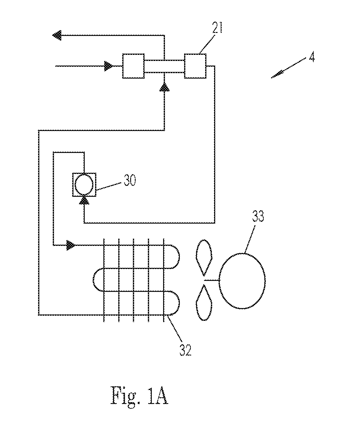
(f) do not provide for multiple cooling zones through independent heat exchangers.
(h) have no means of redirecting excess waste heat-generated electrical power to applications outside the HVAC system.
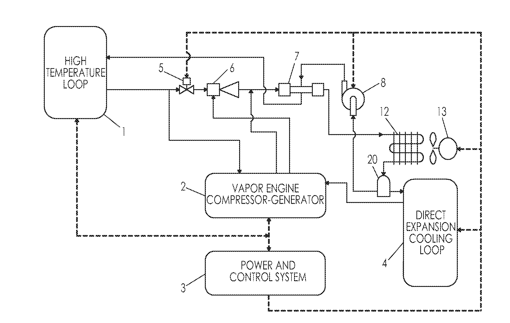
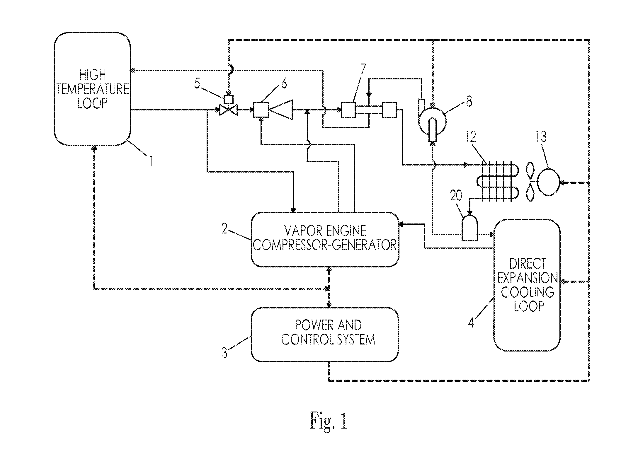
(i) do not provide for a vapor-powered engine-driven mechanical ejector boost compressor or the ability to optimize the efficiency of such a compressor by adjusting the vapor inlet and discharge valve timing.
(j) do not provide for a vapor-powered engine-driven electrical power generator or the ability to optimize the efficiency of this generator by adjusting the vapor inlet and discharge valve timing.
(m) do not continuously optimize the system high-side pressure by adjusting the rate of flow of liquid refrigerant into the boiler.

Method used


Image

  • Mechanically Enhanced Ejector HVAC and Electric Power Generation System
  • Mechanically Enhanced Ejector HVAC and Electric Power Generation System
  • Mechanically Enhanced Ejector HVAC and Electric Power Generation System

Examples


examples

[0097]Typical sources of energy input for Class 8 truck in various operating environments

[0098]System COP=total system capacity / non-waste heat energy input

EXAMPLE 1Operation Condition:Engine off at rest stop in hotclimate-no utility grid connectionAir Conditioning   3 kWRequirement:Heating Requirement:NONESystem COP*:0.92Non-Waste Energy 3.25 kWInput Required:Thermal Sources:Fuel-fired heat*-3.10 kWRecovered air-conditioning heat-0.50 kWElectrical Sources:System generated from fuel-fired heat-0.80 kWStored energy from battery*-0.15 kW

EXAMPLE 2Operation Condition:Engine off at rest stop in hot climate-with utility grid connectionAir Conditioning   3 kWRequirement:Heating Requirement:NONESystem COP*:2.44Non-Waste Energy 1.23 kWInput Required:Thermal Sources:Recovered air-conditioning heat-0.20 kWElectrical Sources:Utility Grid*-1.23 kW

EXAMPLE 3Operation Condition:Engine off at rest stop in cold climate-no utility grid connectionAir Conditioning NONERequirement:Heating Requirement:  2 ...


PUM


Abstract

An HVAC system that uses a mechanical compressor powered by vaporized refrigerant and / or electric power, to increase efficiency in a jet ejector cooling cycle. The device is further able to convert thermal energy to electric power which may be used to meet internal or external requirements, for example, to activate control a system or charge a battery. Compatible input power includes only thermal energy, only electric energy or a combination of the two. Motive thermal energy may be input at a wide range of temperature and include both waste and non-waste heat sources such as that from an internal combustion engine and fuel-fired heater. Solar thermal and solar photovoltaic may also be used when collected from either concentrated or non-concentrated sources. Embodiments of the device are equally well suited to both mobile and stationary applications.

Description

CROSS REFERENCE TO RELATED APPLICATION[0001]NoneFEDERALLY SPONSORED RESEARCH[0002]NoneSEQUENCE LISTING OR PROGRAM[0003]NoneBACKGROUND[0004]1. Field[0005]This application relates to a system which provides heating, air-conditioning and electrical power generation, specifically to such a system which incorporates a mechanically-enhanced vapor ejector compressor and is powered from thermal input energy.[0006]2. Prior Art[0007]The ability to accurately control the air temperature of human occupied compartments is highly desirable for personal comfort in all situations and a serious matter of safety in some. Because heating and air conditioning are energy-intensive, the financial and environmental cost to provide this temperature control is almost entirely determined by the efficiency of the heating, ventilation and air-conditioning (HVAC) equipment and cost of the energy that is used to power it. For a manufacturer of HVAC systems, it would seem logical to address the largest possible m...

Claims


Application Information

Patent Timeline
Patent Type & Authority Applications(United States)
IPC IPC(8): F25B27/00F25B1/06F25B27/02
CPCB60H1/00435B60H2001/3298F25B2400/141F25B25/00F25B1/06F25B1/08
Inventor ALSTON, GERALD ALLEN
Owner ALSTON GERALD ALLEN
Why Eureka
Try Eureka