
Expansion and sensing tool

a sensing tool and expansion technology, applied in the field of integrated expansion and sensing tools, can solve the problems of enlarged wellbore diameter, high directional trajectories of wells, and uncertainty in drilling dynamics, and achieve the effects of minimizing vibration, optimizing drilling efficiency, and accurate inpu

Active Publication Date: 2011-10-13
SMART REAMER DRILLING SYST LTD
View PDF25 Cites 54 Cited by
  • Summary
  • Abstract
  • Description
  • Claims
  • Application Information

AI Technical Summary

Benefits of technology

[0043]The present invention optimizes drilling efficiency by identifying the optimal operational parameters to ensure minimized vibration thereby increasing tool life and minimizing the need for corrective underreaming runs by providing real-time drilling dynamics data which allows the driller to respond earlier thereby saving time and money.
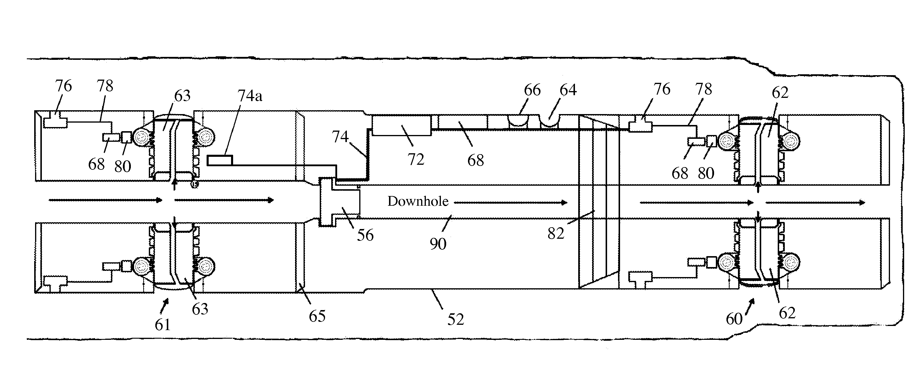
[0044]It is thus an object of the present invention to provide sensors integrated within an underreamer, enabling the integrated device to give immediate measurement of the vibration levels sustained during the wellbore-widening operation and, if these are found to be critically high, to automatically reconfigure drilling parameters to bring vibration levels to satisfactory levels in real-time or to perform such analysis in memory mode and provide input for drilling dynamics models.
[0059]In accordance with a particularly preferred aspect of the invention, the cutter block is provided with an internal duct for directing drilling fluid from a source to an external nozzle among the cutter elements. The source of drilling fluid may be the drill-string or other support for the tool, and the aforementioned through passage for the flow of drilling fluid from the drill string to the drill bit. Alternatively or additionally, the tool body may be provided with an internal duct receiving a source of drilling fluid flowing to an external nozzle adjacent the set of cutters. In each case, the nozzle provides a fluid flow that can help to keep the cutters clean and prevent the build-up of clogging debris from the reaming operation, remove such material altogether from the underreaming zone, and provide a cooling and lubricating function for the cutters.
[0061]In another preferred aspect of the present invention housing for a mechanical calliper is provided within the cutter block which offers a robust location. This has not been possible with previous underreamer blocks due to their inherent design limitations which rely on the block base as a retention mechanism or hydraulic activation through drilling fluid pressure.
[0065]In accordance with the method of the invention, the tool may be provided with expansion element extension control means responsive to dimension data received from the sensor means. In this way, an integrated tool which is capable of detecting vibrations and correcting it may be realised. The drilling dynamics data may prompt a surface monitor to signal an opportunity for operator intervention.

Problems solved by technology

Scarcity of oil and gas is driving oil and gas companies to explore and develop reserves in more challenging basins such as those in water-depths exceeding 6,000 ft (1830 m) or below massive salt sections.
These wells have highly complex directional trajectories with casing designs including 6 or more well sections.
To those skilled in the art, it is known that underreaming activities generate uncertainty as to drilling dynamics and enlarged wellbore diameter.
This is because the prior art does not provide for drilling dynamics data acting on the underreamer.
Consequently, the lack of underreaming dynamics and vibration data results in a limited understanding of the actual loads and forces acting on the underreamer in real-time.
Typically, an underreaming run has no means of investigating drilling dynamics at the underreamer and therefore corrective actions are limited to reducing the rate of penetration, reducing the rotary speed, reducing the weight on bit.
Previously, this would not be possible and drilling delays could occur.
These are unsatisfactory as they there are no actual underreaming drilling dynamics measurements whether direct or inferred.
It is unsatisfactory to depend on indirect indicators such as whether cutter blocks are open or closed or whether fluid pathways are open and a pressure spike is seen at the rig floor to indicate activation.
Such indicators do not provide actual measurements of the underreamed well-bore underreamed nor do they provide verification of underreaming performance; they simply give information on the mechanical or hydraulic status of an aspect of the tool which may or may not lead to the desired well diameter.
Prior art underreamers do not provide for in-situ data measurements on drilling dynamics or loads and therefore their performance, design or configuration cannot be optimized from one job to another.
A major drawback of prior art underreamers is their cutting performance in terms of maintaining similar rates of penetration to the bit.
Further cutter element placements and nozzle locations are optimized in the drill-bit and not necessarily so in the underreamer and this often leads to the bit outperforming the underreamer.
Consequently, this leads to either a separate underreaming run after drilling the section, or leads to the underreaming-while-drilling itself taking several attempts before a complete section is underreamed satisfactorily.
The prior art underreamers do not provide for measurements of the drilling dynamics concentrated at the underreamer.
Therefore, the prior art does not lend itself to a reliable or certain means of measuring underreaming drilling dynamics in real-time or memory mode.
Further the prior art perpetuates drilling inefficiencies due to the uncertainty of actual vibrations at the underreamer.
Further the prior art does not provide for accurate input into underreaming and drilling models.
Further the prior art does not allow for the timely identification of vibration modes or their correction in real-time.

Method used


Image

  • Expansion and sensing tool
  • Expansion and sensing tool
  • Expansion and sensing tool

Examples


Embodiment Construction

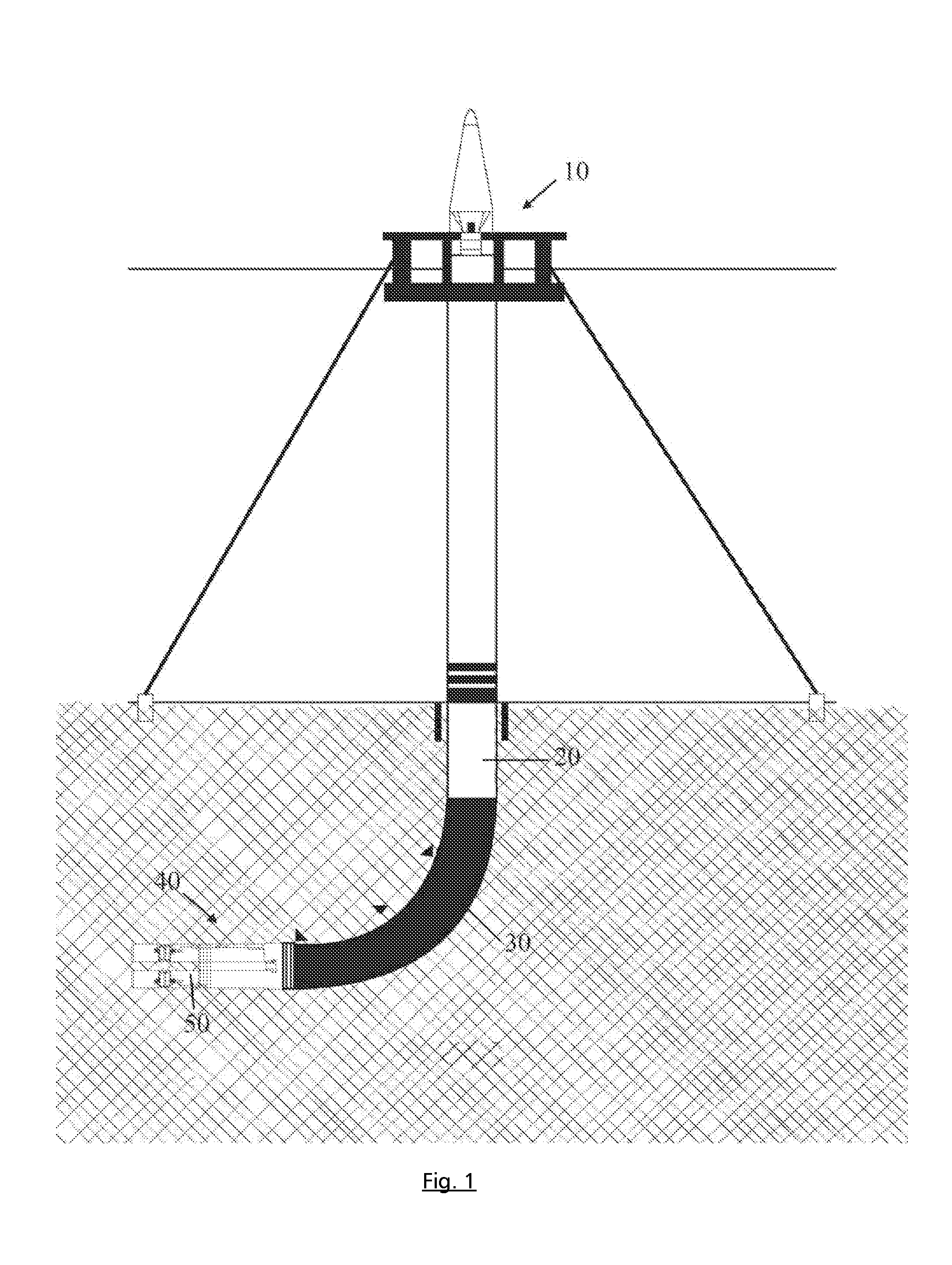
[0076]As shown in FIG. 1, an exemplary exploration or production rig comprises a surface structure 10 at the wellhead, a wellbore 20, and a drill string 30 in the wellbore with a bottom-hole assembly 40 at its lower end. The bottom-hole assembly includes an underreamer sensing tool 50 in accordance with the invention, and a drill-bit (not shown).

[0077]The integrated expansion and sensing tool 50 is illustrated in FIGS. 2a and 2b, and comprises a tubular steel body 52 provided with a drilling collar 54 at its downhole end and a mud-pulser 56 at its other end, which is adapted to be engaged by a further drill collar (not shown) to connect it other elements of the bottom-hole assembly 40, and then to the drill string 30.

[0078]The tool body also carries a vibration sensor 76 and an expansion element assembly 60 between the vibration sensor and the drill collar 54. The expansion element assembly 60 comprises a number of expansion blocks 62 disposed symmetrically, radially around the tool...


PUM


Abstract

An expansion and sensing tool (50) comprising a tool body, cutter blocks and sensors with means for attachment to a drilling support and rotation which permits simultaneous underreaming and measurement of the diameter of a wellbore (40) drilled by an oil and gas rig (10) and characterized by radially extendable cutter blocks (62) incorporating positional sensors (80) adapted to measure the position of the cutter block relative to the tool, and vibration sensor means (76) to measure vibration and underreaming dynamics wellbore dimension in real-time, all of which are inter-linked by a means of communication using receivers, sensors and microprocessors to deliver a desired wellbore depth by simultaneously comparing and correlating measured vibration data and optimizing underreaming parameters. The tool may be optionally configured with calliper or stabilizer means directly or indirectly connected to the underreamer.

Description

CROSS-REFERENCE TO RELATED APPLICATIONS[0001]This application is a continuation-in-part of U.S. Ser. No. 12 / 966,195, WO 2009 / PCT, 156552 A1 and GB0811815.0 (Jun. 27, 2008) granted GB2465504.[0002]Applicant Rasheed, Wajid[0003]U.S. application Ser. No. 12 / 966,195[0004]Country USA[0005]Priority WO 2009 / PCT 156552 A1 and GB0811815.0 (Jun. 27, 2008) granted GB2465504FIELD OF THE INVENTION[0006]This invention relates to an integrated expansion and sensing tool that is capable of enlarging and measuring borehole and tubular diameters, especially wellbores in the oil and gas industry. The tool finds particular use as an underreamer capable of sensing vibration, but can also be configured with other sensors such as callipers to measure wellbore diameter.[0007]When constructing an exploration or production well, numerous downhole operations are conducted to drill and measure a borehole so that it meets the desired well-plan. Drilling itself may utilise a reamer to ensure that the hole diamet...

Claims


Application Information

Patent Timeline
IPC IPC(8): E21B49/00E21D1/06B26B21/54E21B47/08
CPCE21B10/32E21B47/09E21B47/01E21B47/082E21B10/34A01N37/20A01N43/82A01N43/78A01N43/713A01N57/14A01N43/40A01N43/20A01N43/12A01N43/10A01N43/653E21B44/00E21B47/08E21B10/327E21B7/064E21B10/26E21B10/322A01N37/22A01N37/26A01N43/80A01N47/12A01N47/16A01N47/38A01N2300/00E21B7/28E21B33/124E21B47/12E21B49/00E21B47/013E21B47/095B26B21/54E21B10/40E21B47/085
Inventor RASHEED, WAJID
Owner SMART REAMER DRILLING SYST LTD
Learn More