Welding arc termination method and system

a technology of welding arc and termination method, which is applied in the field of welding systems, can solve the problems of mark on the workpiece, the capacitor bank is not always discharged, etc., and achieve the effect of reducing the conduction angl

Active Publication Date: 2011-10-13
ILLINOIS TOOL WORKS INC
View PDF6 Cites 0 Cited by
  • Summary
  • Abstract
  • Description
  • Claims
  • Application Information

AI Technical Summary

Benefits of technology

[0004]In an exemplary embodiment, a method for controlling a welding process includes receiving a signal indicating an operator intention to terminate a welding arc and stopping advance of a welding wire in response to the signal. The method also includes reducing a conduction angle for switching of solid state switches that generate welding power in response to the signal.

Problems solved by technology

Unfortunately, a capacitor bank is not always discharged after a welding operation is complete and before an operator resumes a welding operation by making contact between a welding wire and a workpiece.
When this occurs, the stored energy in the capacitor bank may cause the welding wire to stick to the workpiece or cause a mark on the workpiece.

Method used


Image

  • Welding arc termination method and system
  • Welding arc termination method and system
  • Welding arc termination method and system

Examples


Embodiment Construction

[0014]As described in detail below, embodiments of a weld arc termination system and method are provided. For example, power to a weld arc may be incrementally decreased after an operator releases a welding torch trigger in order to discharge a capacitive circuit coupled to the welding output. Thus, the welding arc continues over a brief time. In one embodiment, a method for controlling a welding process includes receiving a signal indicating an operator intention to terminate a welding arc and stopping advance of a welding wire in response to the signal. The method also includes reducing a conduction angle for switching of solid state switches that generate welding power in response to the signal.

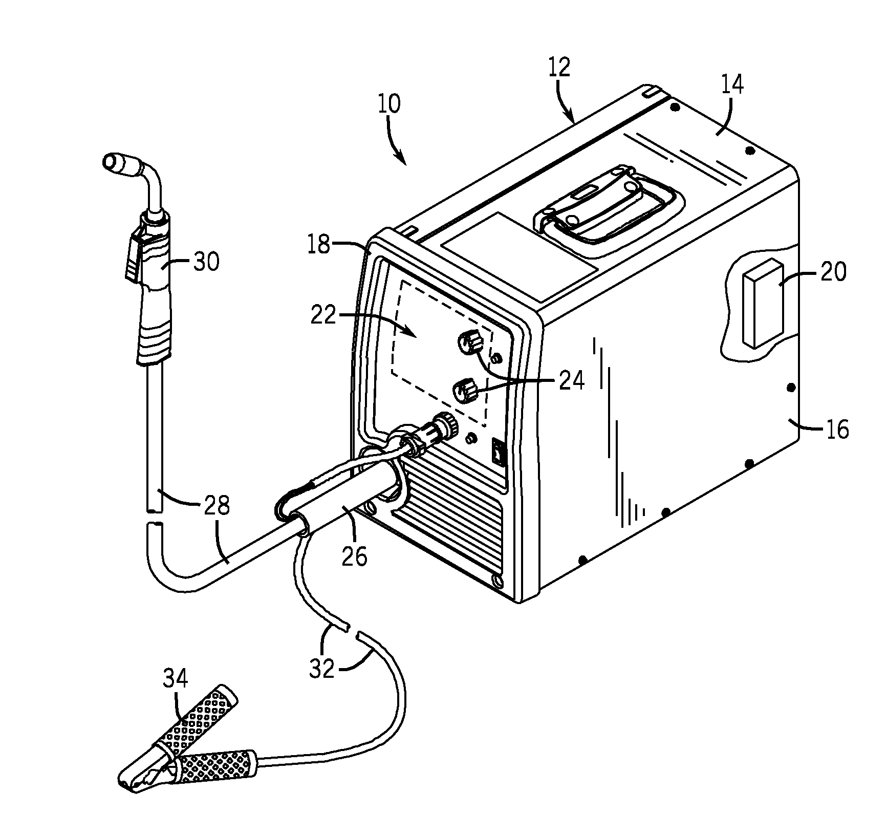
[0015]Turning now to the drawings, FIG. 1 is a perspective view of an exemplary welding power source 10 configured for use in a gas metal arc welding (GMAW) process or a flux cored welding (FCAW) process. The welding power source 10 includes a housing 12 including a top panel 14, a side pa...


PUM

PropertyMeasurementUnit
timeaaaaaaaaaa
timeaaaaaaaaaa
conduction angleaaaaaaaaaa

Abstract

A system and method for welding arc termination are provided. In an exemplary embodiment, a method for controlling a welding process includes receiving a signal indicating an operator intention to terminate a welding arc and stopping advance of a welding wire in response to the signal. The method also includes reducing a conduction angle for switching of solid state switches that generate welding power in response to the signal.

Description

CROSS REFERENCE TO RELATED APPLICATIONS[0001]This application is a Non-Provisional patent application of U.S. Provisional Patent Application No. 61 / 322,612 entitled “Method For Improving Arc Ends”, filed Apr. 9, 2010, which is herein incorporated by reference.BACKGROUND[0002]The invention relates generally to welding systems and, more particularly, to methods and systems that may be utilized to terminate a welding arc generated by a welding system.[0003]Welding is a process that has become ubiquitous in various industries for a variety of types of applications. For example, welding processes, such as tungsten inert gas (TIG) welding and metal inert gas (MIG) welding, are utilized in industries such as shipbuilding, construction, manufacturing, and so forth. Welding power sources are utilized to provide power for such applications. Welding power sources typically include capacitor banks that are charged during a welding operation and should be discharged when a welding operation is c...

Claims


Application Information

Patent Timeline
Patent Type & Authority Applications(United States)
IPC IPC(8): B23K9/10
CPCB23K9/1012
Inventor KNOENER, CRAIG STEVEN
Owner ILLINOIS TOOL WORKS INC
Why Eureka
Try Eureka