Image processing apparatus, imaging apparatus, and computer readable medium

a technology of image processing and imaging apparatus, which is applied in the field of image processing apparatus, imaging apparatus and computer readable medium, can solve the problems of blurred image of subject, inability to properly reduce noise, and difficulty in distinguishing between motions of subjects

Active Publication Date: 2011-10-13
NIKON CORP
View PDF6 Cites 13 Cited by
  • Summary
  • Abstract
  • Description
  • Claims
  • Application Information

AI Technical Summary

Benefits of technology

[0048]A computer readable medium storing an image processing program of the present application makes a computer execute an input step reading a target image being a noise reduction target and a reference image to be a reference of a noise reduction processing, a first coefficient determination step determining a value of a first coefficient based on a difference between the target image and the reference image, a second coefficient determination step determining a value of a second coefficient based on brightness information of any one of the target image, the reference image, and both the target image and the reference image, and a noise reduction step reducing a noise superimposed on the target image by performing a weighted addition on the target image and the reference image by using the value of the first coefficient and the value of the second coefficient.
[0049]A computer readable medium storing an image processing program of the present application makes a computer execute an input step reading a target image being a noise reduction target and a reference image to be a reference of a noise reduction processing, a reduced image generation step generating a pair of a first reduced image obtained by reducing the target image and a second reduced image obtained by reducing the reference image at a same reduction ratio as a reduction ratio of the first reduced image, at least one reduction ratio, a first coefficient determination step determining a value of a first coefficient based on a difference between the first reduced image and the second reduced image, a second coefficient determination step determining a value of a second coefficient based on brightness information of any one of the first reduced image, the second reduced image, and both the first reduced image and the second reduced image, and a noise reduction step performing a weighted addition on the first reduced image and the second reduced image by using the value of the first coefficient and the value of the second coefficient, extracting a noise in a frequency band corresponding to the reduction ratio, and reducing the noise in the frequency band from the target image.

Problems solved by technology

However, the conventional technology has a problem that, when a noise intensity is high, even when a subject is not moved, a variation in pixel values of respective pixels is large, so that it becomes difficult to distinguish between a motion of the subject and a noise, resulting in that noise reduction cannot be properly conducted.
Further, in the conventional technology, although a filter coefficient is determined based on a detection result of a motion part of a subject, noise reduction of a current frame using the filter coefficient is performed through synthetic processing using simple weighting between the current frame and a noise-reduced past frame which is one frame before the current frame, so that an image of the subject may be blurred.
Further, in the conventional technology, since a filter coefficient is determined based only on a difference in pixel values between frames, there is a case where a noise cannot be correctly reduced from a pixel having a pixel value with a high noise level, such as a dark part of a subject, for example.

Method used


Image

  • Image processing apparatus, imaging apparatus, and computer readable medium
  • Image processing apparatus, imaging apparatus, and computer readable medium
  • Image processing apparatus, imaging apparatus, and computer readable medium

Examples


first embodiment

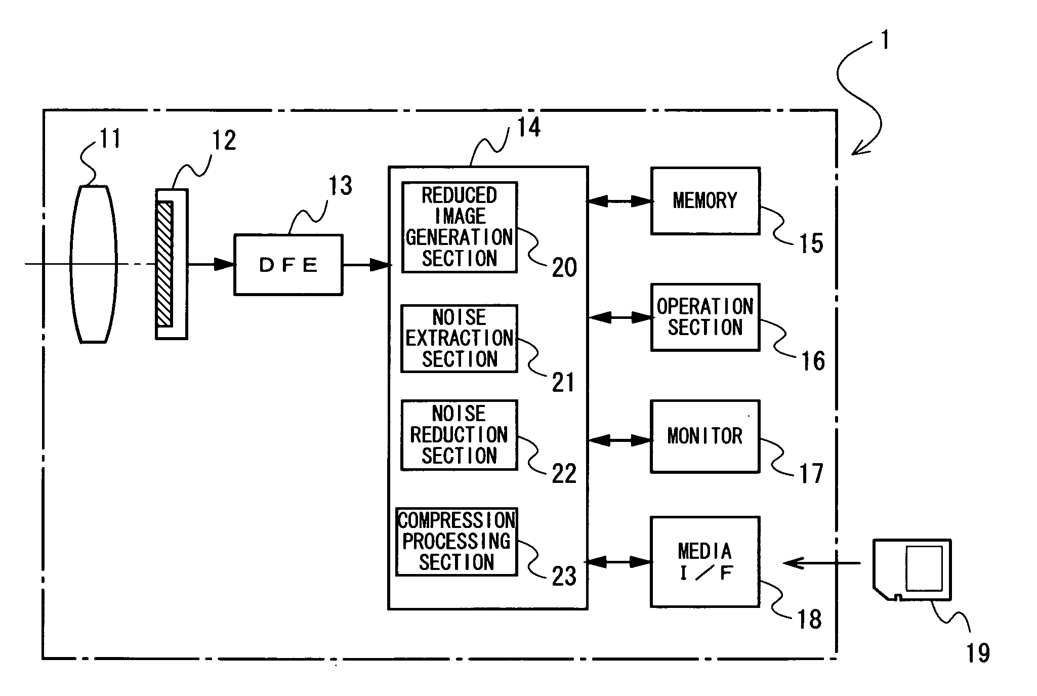
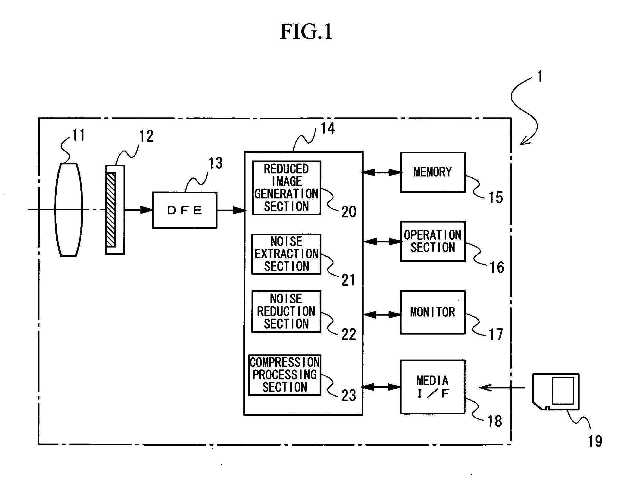
[0072]FIG. 1 is a block diagram illustrating an example of a configuration of a digital camera 1 according to a first embodiment.

[0073]The digital camera 1 of the present embodiment includes an imaging optical system 11, an image sensor 12, a DFE 13, a CPU 14, a memory 15, an operation section 16, a monitor 17 and a media I / F 18. Here, the DFE 13, the memory 15, the operation section 16, the monitor 17 and the media I / F 18 are respectively connected to the CPU 14.

[0074]The image sensor 12 is a device capturing a subject image formed by a luminous flux that passes through the imaging optical system 11. An output of the image sensor 12 is connected to the DFE 13. Note that the image sensor 12 of the present embodiment may also be a progressive scanning type solid-state image sensor (CCD or the like) or an XY address type solid-state image sensor (CMOS or the like).

[0075]On a light-receiving surface of the image sensor 12, a plurality of light-receiving elements are arranged in a matri...

second embodiment

[0105]A digital camera according to a second embodiment of the present application has the same configuration as that of the digital camera 1 according to the first embodiment in FIG. 1, so that detailed explanation of respective components will be omitted.

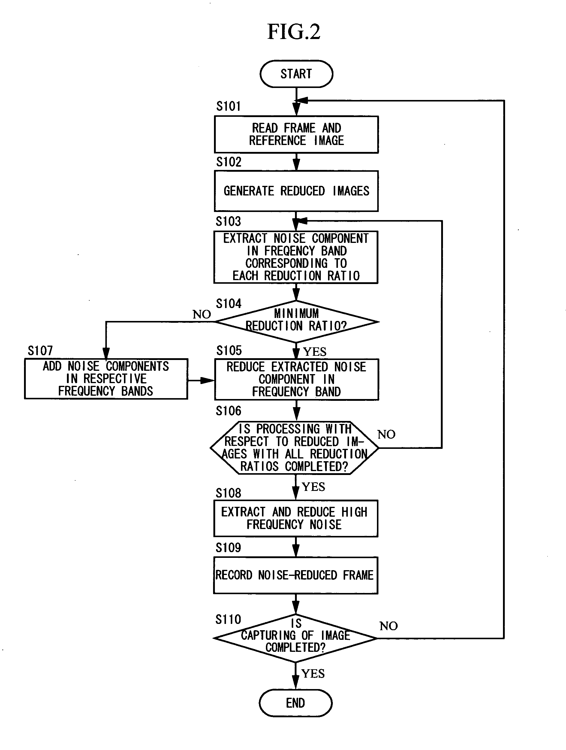
[0106]FIG. 4 illustrates a flow chart of a processing operation performed by a digital camera 1 of the present embodiment. In FIG. 4, processing similar to that of the first embodiment illustrated in FIG. 2 is denoted by a step number whose last two digits are the same as those of the step number of the processing in the first embodiment, and detailed explanation thereof will be omitted.

[0107]FIG. 5 illustrates a flow of image data in the processing illustrated in FIG. 4. In FIG. 5, image data which are the same as the image data in the first embodiment illustrated in FIG. 3 are denoted by the same reference numerals and letters, and detailed explanation thereof will be omitted.

[0108]A point in which the processing operation perfo...

third embodiment

[0114]FIG. 6 is a block diagram illustrating an example of a configuration of a digital camera 1′ according to a third embodiment.

[0115]In the digital camera 1′ according to the present embodiment, a component which operates in the same manner as the component of the digital camera 1 according to the first embodiment illustrated in FIG. 1 is denoted by the same reference numeral, and detailed explanation thereof will be omitted.

[0116]A reduced image generation section 50 generates a reduced image of each frame of a moving image captured by the image sensor 12. The reduced image generation section 50 generates a reduced image of each frame (target image) at one reduction ratio of 1 / 4 (first reduced image). Note that the reduced image generation section 50 of the present embodiment does not generate a reduced image of a reference image to be a reference of noise reduction processing. Further, the reduced image generation section 50 may also generate a plurality of reduced images of th...


PUM


Abstract

An image processing apparatus of the present application includes a reduced image generation section generating a first reduced image obtained by reducing at least a target image being a noise reduction target, out of the target image and a reference image to be a reference of a noise reduction processing, a noise extraction section extracting a noise component in a frequency band corresponding to a reduction ratio of the first reduced image by using at least the first reduced image, and a noise reduction section reducing the noise component in the frequency band from a pixel value of each pixel of the target image based on the noise component in the frequency band being extracted.

Description

CROSS REFERENCE TO RELATED APPLICATIONS[0001]This application is based upon and claims the benefit of priorities from Japanese Patent Application Nos. 2010-077977, 2010-215609, 2010-262746, and 2011-035419, each filed on Mar. 30, 2010, Sep. 27, 2010, Nov. 25, 2010, and Feb. 22, 2011, the entire contents of which are incorporated herein by reference.BACKGROUND[0002]1. Field[0003]The present application relates to an image processing apparatus, an imaging apparatus and a computer readable medium.[0004]2. Description of the Related Art[0005]Conventionally, noise reduction processing with respect to a moving image has been required to be performed in consideration of a motion of captured subject, in which since the number of flames to be processing targets is large, a calculation amount and a circuit scale are increased.[0006]In order to solve those problems, for example, there has been developed a technology in which a motion part of a subject is detected based on a difference between ...

Claims


Application Information

Patent Timeline
Patent Type & Authority Applications(United States)
IPC IPC(8): G06K9/40G06K9/00H04N5/217G06K9/36
CPCG06T5/002H04N5/217G06T2207/20016H04N23/81
Inventor ITO, YUICHI
Owner NIKON CORP
Why Eureka
Try Eureka