Image reading apparatus and optical module using the same

a technology of image reading apparatus and optical module, applied in the field of image reading apparatus, to achieve the effect of low cost, high accuracy and convenient design and manufactur

Inactive Publication Date: 2011-10-13
SONY SEMICON SOLUTIONS CORP
View PDF14 Cites 20 Cited by
  • Summary
  • Abstract
  • Description
  • Claims
  • Application Information

AI Technical Summary

Benefits of technology

[0019]According to the image reading apparatus and the optical module of the embodiment of the invention, since a plurality of lens arrays, as an image forming means for forming erected images, have an identical shape and an identical property and are formed by integral molding of a plurality of lenses, it is possible to mold the lens arrays using a common metal mold and to easily design and manufacture the respective lens arrays with high accuracy at a low cost.
[0020]In addition, since at least an aperture is interposed between the plurality of lens arrays and therefore it is possible to prevent overlapping of images between adjacent lenses, it is possible to suppress degradation in the resolution even when a gap caused by a subject occurs and, ultimately, to enlarge the depth of focus. In addition, since just the aperture is necessary to be inserted at least between the lens arrays, the structure becomes simple, which contributes to the simplification and cost reduction of the design and manufacturing of the apparatus.

Problems solved by technology

(1) In the manufacturing process, it is necessary to mold a glass material in a fine fiber shape and to form an index of refraction distribution in the moving radius (radius) direction.
(2) It is necessary to cut the fiber-shaped glass compacts into segments with the same length so as to produce individual rod lenses and to precisely line up the rod lenses in parallel with an array format so as to planarize the cut end surface, thereby preventing scattering or the like.
(3) It is necessary to cover the outer circumference of the glass in the respective rod lenses with a black resin or the like so that light incident on the respective rod lenses does not cause cross talk with adjacent rod lenses.

Method used


Image

  • Image reading apparatus and optical module using the same
  • Image reading apparatus and optical module using the same
  • Image reading apparatus and optical module using the same

Examples


Embodiment Construction

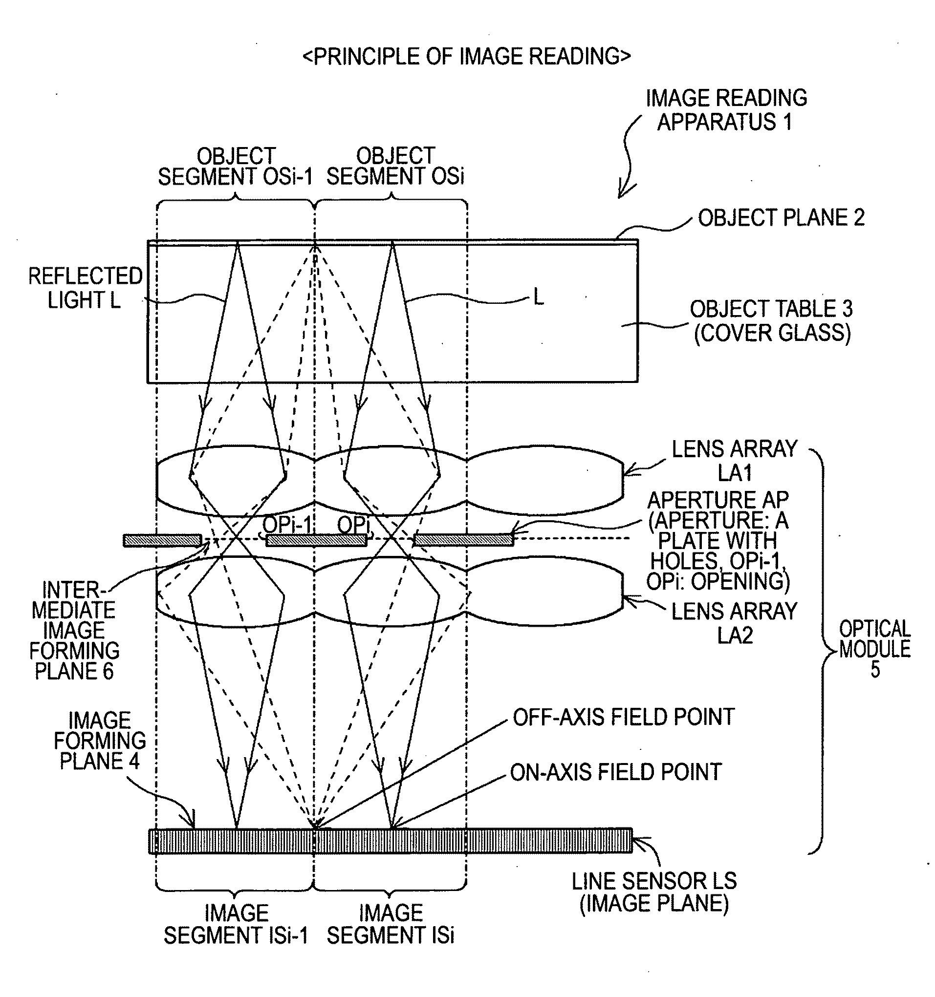
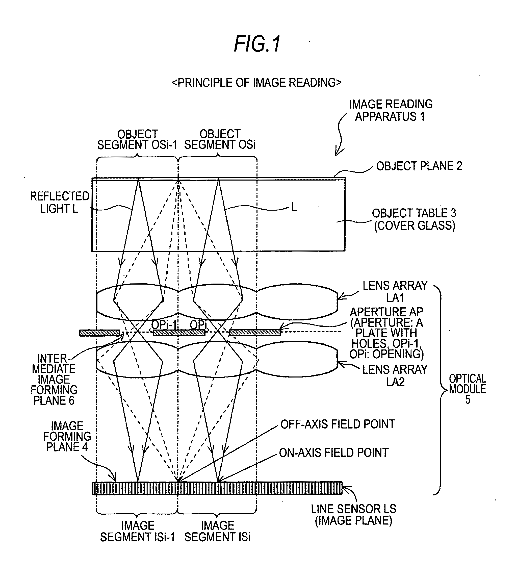
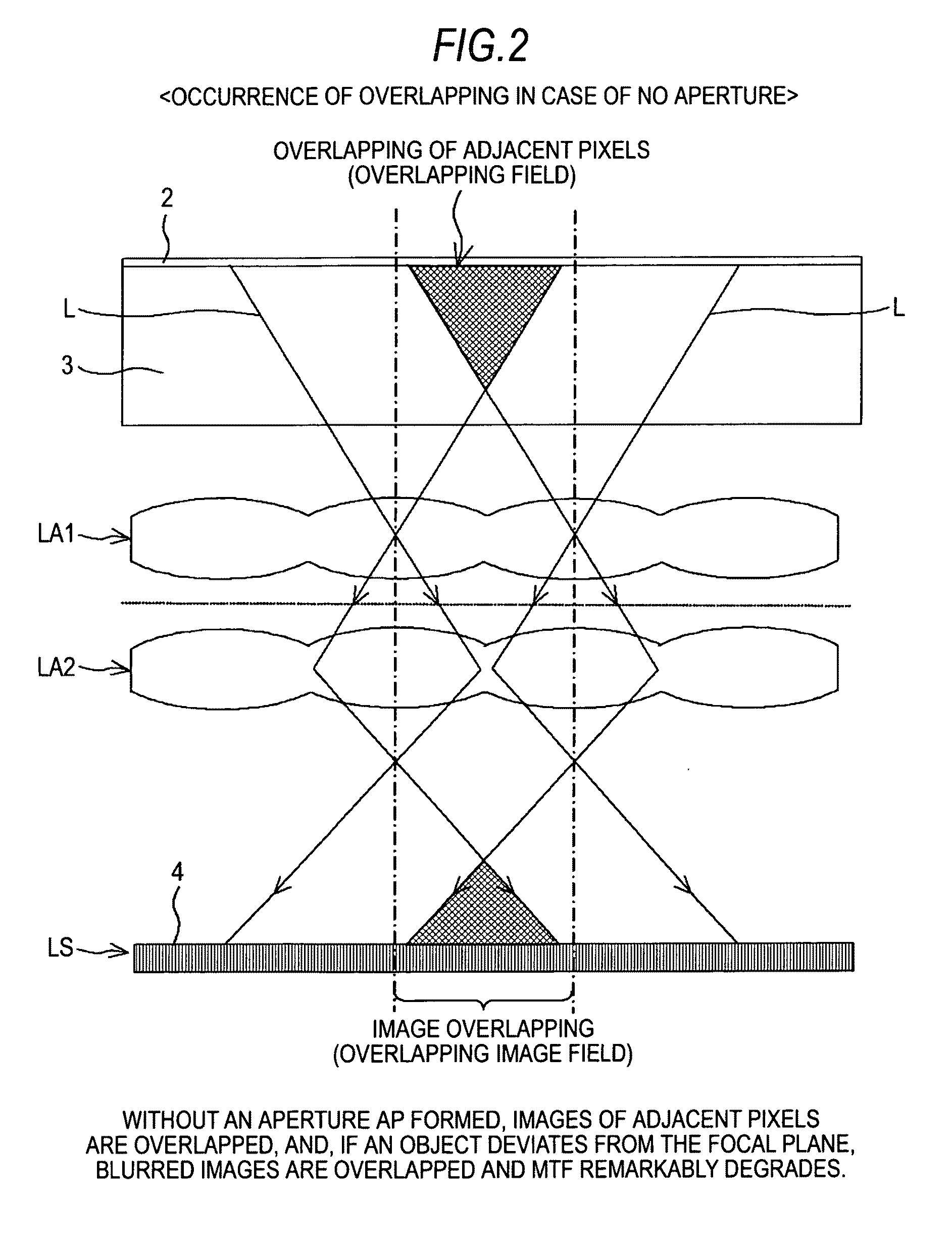
[0037]In an image reading apparatus and an optical module of an embodiment of the invention, it is necessary to dispose an aperture, among the middle position, the light incidence side and the light reflection side of a plurality of lens arrays, at least at the middle position to realize the above-described effects, and interposing apertures at the light reflection side and, furthermore, at the light incidence side enables suppression of cross talk by light between adjacent lenses and is advantageous for enlargement of the depth of focus.

[0038]In addition, since a subject is disposed at a position closer to an image forming unit than the focal plane of the image forming unit formed at a side of the subject, it is possible to obtain high-definition images with a high MTF even when the depth of focus is enlarged or to enlarge the depth of focus at which high definition may be obtained.

[0039]Furthermore, since a light irradiating unit, the image forming unit, a aperture and the photoel...


PUM


Abstract

An image reading apparatus includes: alight irradiating means for irradiating light to a subject having images to be read; an image forming means for making the light from the subject incident on an image plane so as to form images as erected images; and a photoelectric conversion means for converting the incident light of the erected images into image signals, wherein the image forming means is constituted of a plurality of lens arrays that have a mutually identical shape and property and are sequentially disposed, sharing common light axes, between the subject and the photoelectric conversion means, and the respective lens arrays are formed by integral molding of a plurality of lenses, and an aperture provided with light passing holes with the light axes as the center is interposed at least between the plurality of lens arrays, and areas other than the light passing holes in the aperture form light shielding areas.

Description

BACKGROUND OF THE INVENTION[0001]1. Field of the Invention[0002]The present invention relates to an image reading apparatus, such as an image scanner or the like, having a light irradiating means for irradiating, for example, linear light to a subject, such as an object having images to be read, an image forming means, such as a linear lens array or the like, for making the light from the subject incident on an image plane so as to form images as erected images, and a photoelectric conversion means for converting the incident light of the erected images into image signals; and an optical module constituted by unitizing the light irradiating means, the image forming means and the photoelectric conversion means. 2. Description of the Related Art[0003]In an image reading apparatus, such as a copy machine or a peripheral device and a multifunction machine using the same, an image scanner, a facsimile or the like, in the related art, copying, printing or the like has been performed by ma...

Claims


Application Information

Patent Timeline
Patent Type & Authority Applications(United States)
IPC IPC(8): H04N1/04
CPCH04N1/02825H04N2201/02431H04N2201/02497H04N2201/02493H04N2201/02458
Inventor KAISE, KIKUO
Owner SONY SEMICON SOLUTIONS CORP
Why Eureka
Try Eureka