Maintaining Time of Day Synchronization

a synchronization and day synchronization technology, applied in the direction of synchronization arrangement, frequency-division multiplex, instruments, etc., can solve the problems of reducing the throughput of data communication, few synchronization schemes proposed, and inability to maintain time synchronization in a tracking mod

Active Publication Date: 2011-10-13
HARRIS GLOBAL COMM INC
View PDF4 Cites 43 Cited by
  • Summary
  • Abstract
  • Description
  • Claims
  • Application Information

AI Technical Summary

Benefits of technology

In a CSMA environment, an estimate of clock drift can be determined from exchanges of RTS and CTS messages. In response to receiving an RTS message from a source node, a destination node records the reception time and sends a CTS message back to the source node. In response to receiving the CTS message, the source node determines the propagation delay from the transmission time of the RTS message, the reception time of the CTS message, and a known turn-around time. The source node supplies the transmission time of the RTS message and the computed propagation to the destination node in the subsequent data message, which allows the destination node to compute the clock drift relative to the source node and to adjust its clock accordingly.

Problems solved by technology

However, under real-world operating conditions, this is often not the case, and some mechanisms must be provided to align the clocks of different communication devices.
However, few, if any, synchronization schemes have been proposed that focus on the problem of maintaining synchronization once it has been established (i.e., synchronization “tracking”).
Once the data communication begins and synchronization is in a tracking mode, it is a problem if the receivers do not know when to tune the communication device to the correct frequency to receive the timing signals.
Thus, valuable data bandwidth can be wasted in the tracking mode waiting for the receiver to search for the timing signals, resulting in reduced throughput for data communications.
Another shortcoming of current TOD synchronization schemes is the inability to maintain time synchronization in a tracking mode after an initial synchronization in an acquisition mode.
While in the tracking mode, initial clock alignments cannot guarantee future clock alignments because of clock drift, and as a result, the network nodes need to search for timing signals for clock alignments.
Thus, network nodes sometimes have difficulty maintaining time synchronization in the tracking mode.
The destination node, however, does not always know the internal delays in the source node, as there can be delays from the beginning time slot of a timing signal to the start of transmission (SOT) of the timing signal.
These delays can be due to the processor, the modem, transmission security, propagation delays and other reasons.
Thus, inaccurate estimations of time delays could lead to problems in achieving time synchronization.

Method used


Image

  • Maintaining Time of Day Synchronization
  • Maintaining Time of Day Synchronization
  • Maintaining Time of Day Synchronization

Examples


example 1

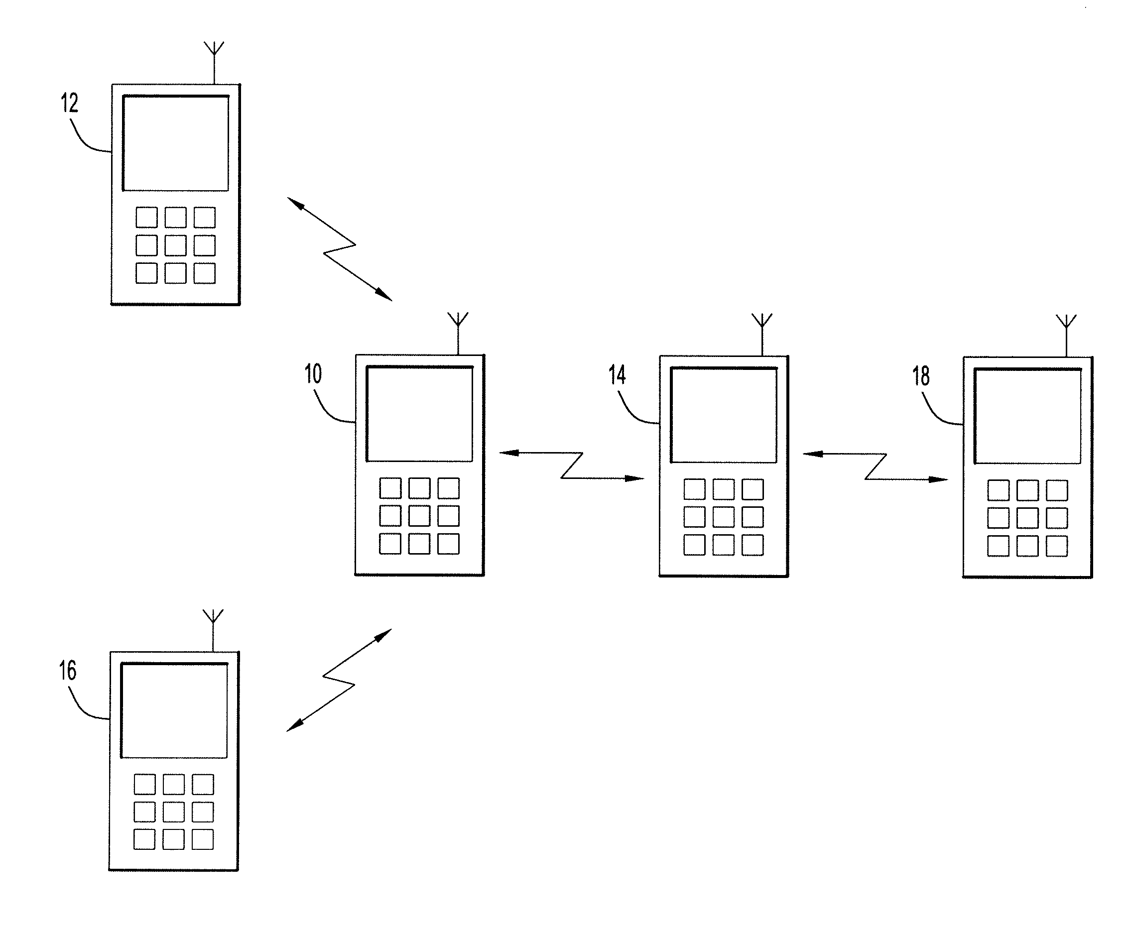
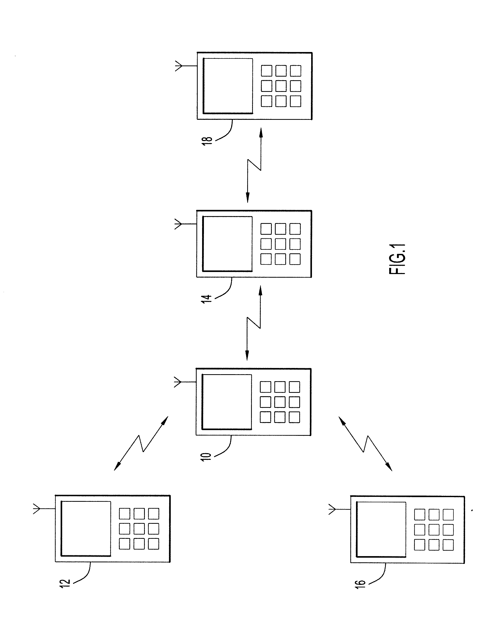
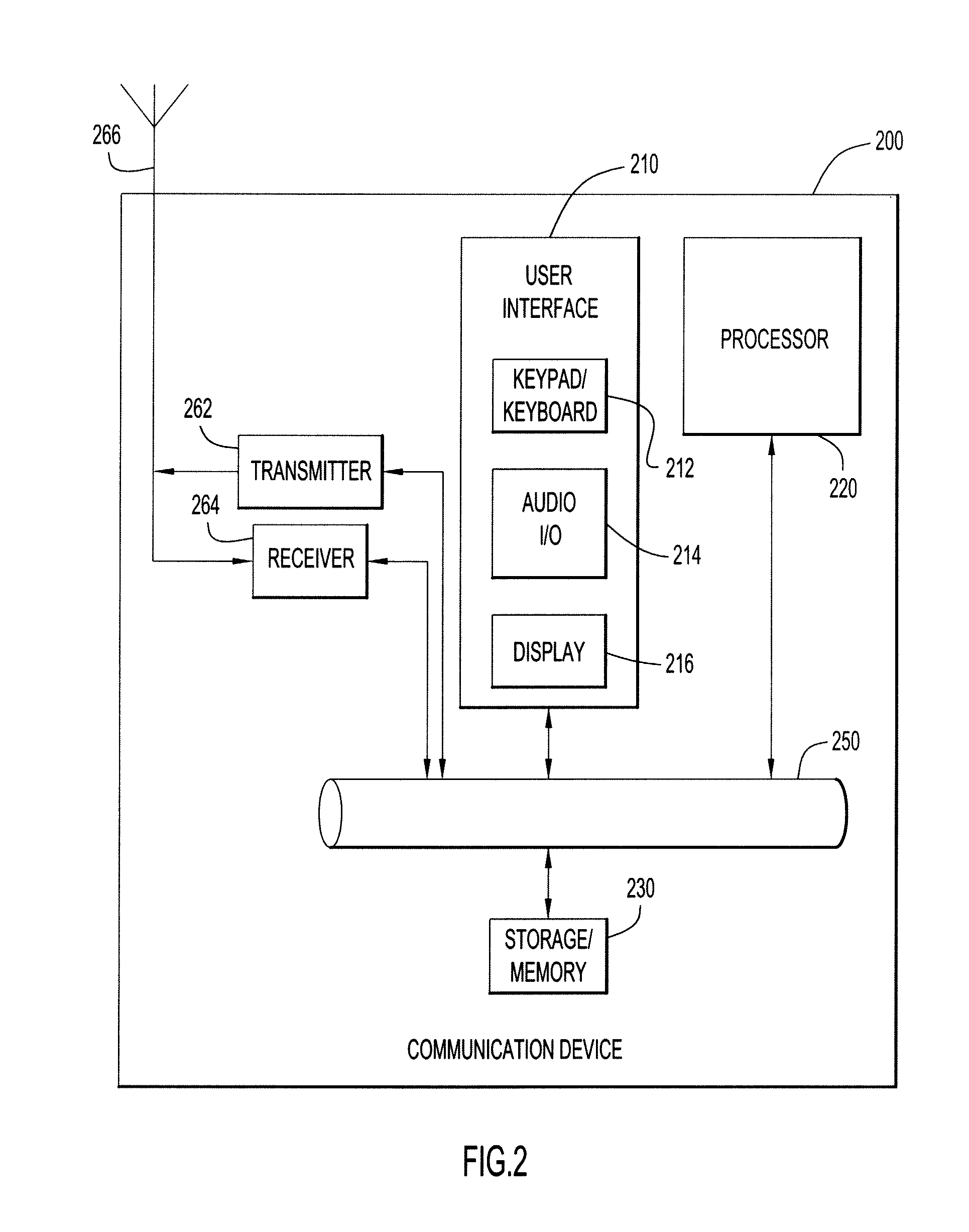
The following example helps illustrate the time synchronization techniques of the present invention in a TDMA environment. The techniques described in this example can be performed by one or more communication devices located at any point throughout the network environment, such as, but not limited to, one or more of the devices shown in FIG. 1 and FIG. 2.

This example assumes that the slot period, S, is 1.5 ms and that each epoch is 90 ms. The example further assumes that each super epoch has 4 epochs, so that N=4, and that at a time 360 sec is aligned with the super epoch boundary. Thus, each super epoch period is 0.36 sec. Timing signals are sent at the first two slots of each super epoch; thus, the points in time at which the timing packets could be sent are: 360 sec., 360.0015 sec., 360.36 sec., 360.3615 sec., 360.72 sec., 360.7215 sec., and so on. The example assumes a 10-node network with successful network formation in the acquisition mode and that all the clocks are synchron...

example 2

The following describes an example to illustrate the time synchronization techniques of the present invention in a CSMA environment. The techniques described in this example can be performed by one or more network devices located at any point throughout the network environment, such as, but not limited to, one or more of the devices shown in FIG. 1 and FIG. 2.

The same assumptions for Example 1, above, are incorporated herein. The available point-to-point packet transmission using CSMA / CA is considered as a bonus to computing the clock drift. Assume at T1=364.341 sec, node 5 sends point-to-point packet to node 4 and the propagation distance between node 5 and node 4 is again 1 km. The relationships among T1, T2, T3, and T4 are the same as in Example 1 and T2=364.34100533 sec, T3=364.34250533 sec and T4=364.34250666 sec. Node 5 first sends an RTS to node 4 at T1=364.341 sec. Node 4 responds with CTS to node 5 at T3, and node 5 receives the CTS at T4. Since there is no timing informati...


PUM


Abstract

A technique for maintaining time synchronization between network nodes involves broadcasting a timing signal from a source node to its neighbors. The timing signal is transmitted in a dedicated source time slot of a super epoch comprising a number of epochs each having a number of time slots. A reply timing signal is received at the source node from a neighboring node designated as the destination node, where the reply timing signal is received in a dedicated destination time slot of the super epoch. The clock drift and propagation delay between the source and destination nodes are computed at the source node. At the neighboring nodes other than the destination node, clock drift can be computed using previous estimates of propagation delay. RTS and CTS exchanges from PTP packets can also be used to estimate the propagation delay in the source node and the clock drift in the destination node.

Description

BACKGROUNDIn wireless and ad-hoc communication networks, time synchronization is often necessary in order for two communication devices to communicate successfully. For channel access using time division multiple access (TDMA), accurate slot alignment requires time of day (TOD) synchronization. For military communications, synchronization is especially important because of the requirements of communication security.Synchronization schemes depend upon the transmission of timing signals for clock alignments. These timing signals could contain timing information in the fraction microsecond range for accuracy. Global positioning system (GPS) signals can be used to establish TOD synchronization. For a communication device with GPS, the GPS timing signal sent internally at the GPS 1 pulse per second (pps) rate can be used to align the local real time clock (RTC) to the GPS clock. If every communication device in the network has GPS, TOD synchronization is straightforward when the GPS prov...

Claims


Application Information

Patent Timeline
Patent Type & Authority Applications(United States)
IPC IPC(8): H04J3/06
CPCH04W56/002H04J3/0667H04J3/0682H04W92/10
Inventor LIU, YU-JIH
Owner HARRIS GLOBAL COMM INC
Why Eureka
Try Eureka