Optically Pumped Laser

a laser and optical pump technology, applied in the field of lasers, can solve the problems of inefficient lasers, high pump power, and difficult utilization, and achieve the effect of high pump power

Inactive Publication Date: 2011-10-13
CORNING INC
View PDF0 Cites 4 Cited by
  • Summary
  • Abstract
  • Description
  • Claims
  • Application Information

AI Technical Summary

Benefits of technology

[0002]Although the concepts of the present disclosure are not limited to green laser sources, in the context of optically pumped green laser sources, the present inventors have recognized that existing blue laser diodes can be convenient optical pump sources but can also be problematic to utilize in a green laser source. Specifically, considering a laser structure consisting of 3-nm thick InGaN quantum wells (QWs) embedded in an InGaN waveguide layer, if such a structure is side-pumped with a blue laser diode beam, then only about 3% of the pump light will be absorbed in a single QW of the active region because the absorption coefficient for blue light in In0.25Ga0.75N is only about 1×105 cm−1. Even if the structure contains 10 quantum wells and the pump light is double-passed, only about 46% of the pump light will ultimately be absorbed. The resulting laser would be inefficient and would require a relatively high pump power to produce the carrier density needed to reach the lasing threshold. Alternatively, if the structure is end-pumped, assuming an optical confinement factor as low as 0.01, the absorption length for the pump light will be about 0.001 cm, which is far shorter than what would be needed to create a working laser. The concepts presented herein relate to optical pump configurations for lasers including, but not limited to, blue-pumped green laser sources and, more particularly, blue-pumped green lasers based on InGaN multi quantum wells (MQW).

Problems solved by technology

Although the concepts of the present disclosure are not limited to green laser sources, in the context of optically pumped green laser sources, the present inventors have recognized that existing blue laser diodes can be convenient optical pump sources but can also be problematic to utilize in a green laser source.
The resulting laser would be inefficient and would require a relatively high pump power to produce the carrier density needed to reach the lasing threshold.

Method used


Image

  • Optically Pumped Laser
  • Optically Pumped Laser
  • Optically Pumped Laser

Examples


Embodiment Construction

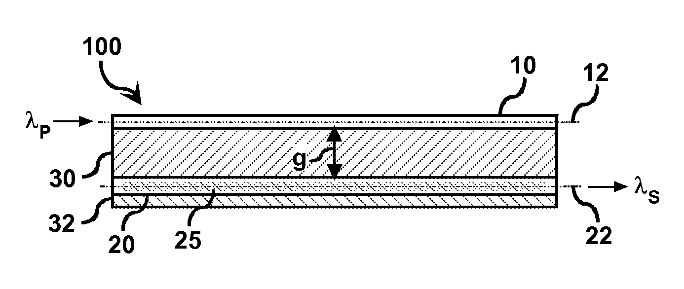
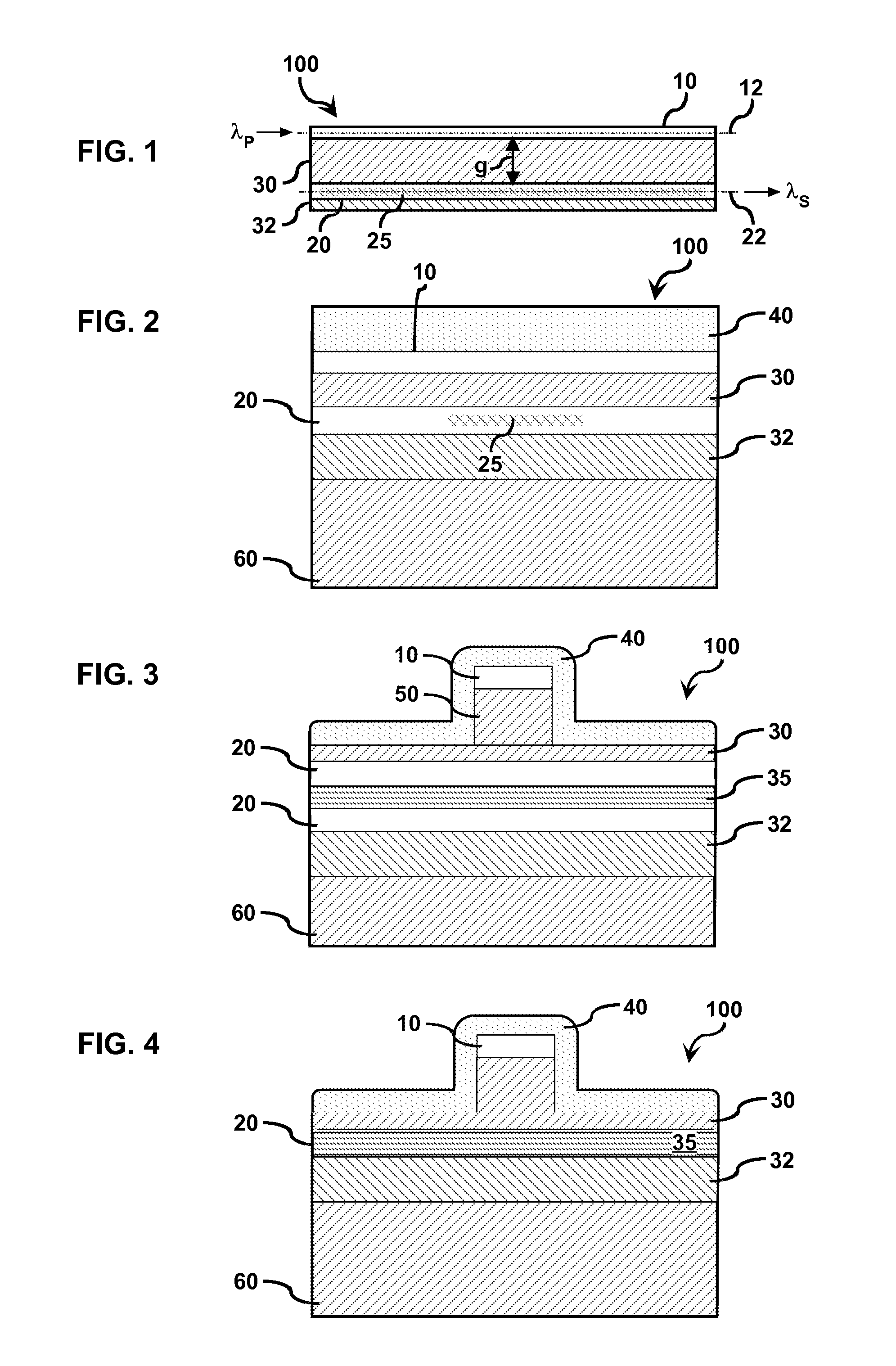
[0008]Referring initially to FIG. 1, a laser 100 is provided comprising a pump waveguide core 10, a signal waveguide core 20, an active gain region 25, and associated waveguide cladding material 30, 32. FIG. 1 illustrates the laser 100 along the longitudinal dimension of the device, while FIGS. 2-4, described in further detail below, are taken along a cross section of the device perpendicular to a longitudinal dimension of the device. As is clearly illustrated in FIG. 1, the pump waveguide core 10 is oriented along a longitudinal optical pumping axis 12 and is at least partially surrounded by cladding material characterized by an index of refraction that is lower than that of the pump waveguide core 10 at a given pump wavelength λP. Similarly, the signal waveguide core 20 is oriented along a longitudinal optical signal axis 22 and is also at least partially surrounded by cladding material. The signal waveguide cladding comprises material that is characterized by an index of refracti...


PUM


Abstract

Concepts of the present disclosure may be employed to optimize optical pumping and ensure high modal gain in the active region of an optically pumped laser source by establishing an optical coupling gap such that the pump waveguide mode field overlaps the active gain region associated with the signal waveguide. The optical coupling gap is tailored to be sufficiently large to ensure that a significant active gain region length is required for absorption and sufficiently small to ensure that the pump waveguide mode field P overlaps the active gain region. In accordance with one embodiment of the present disclosure, the pump waveguide core is displaced from the signal waveguide core by an optical coupling gap g in a lateral direction that is approximately perpendicular to the optical pumping axis. A decayed intensity portion of the pump waveguide mode field extends into the active gain region to optically pump the active gain region and form an optical signal propagating along the longitudinal optical signal axis of the signal waveguide core.

Description

BACKGROUND[0001]The present disclosure relates to lasers and, more particularly, to optically pumped lasers designed to address design challenges associated with pump absorption in the active region of the laser.BRIEF SUMMARY[0002]Although the concepts of the present disclosure are not limited to green laser sources, in the context of optically pumped green laser sources, the present inventors have recognized that existing blue laser diodes can be convenient optical pump sources but can also be problematic to utilize in a green laser source. Specifically, considering a laser structure consisting of 3-nm thick InGaN quantum wells (QWs) embedded in an InGaN waveguide layer, if such a structure is side-pumped with a blue laser diode beam, then only about 3% of the pump light will be absorbed in a single QW of the active region because the absorption coefficient for blue light in In0.25Ga0.75N is only about 1×105 cm−1. Even if the structure contains 10 quantum wells and the pump light i...

Claims


Application Information

Patent Timeline
Patent Type & Authority Applications(United States)
IPC IPC(8): H01S5/34H01S3/091
CPCB82Y20/00G02B2006/12121H01S5/041H01S5/34333H01S5/22H01S5/3213H01S5/1032
Inventor KUKSENKOV, DMITRI VLADISLAVOVICHSIZOV, DMITRYWEST, JAMES ANDREW
Owner CORNING INC
Why Eureka
Try Eureka