Apparatus for and method of measuring workpiece on machine tool

a technology of workpiece and apparatus, which is applied in the direction of programme control, total factory control, instruments, etc., can solve the problems of not being applicable to all machine tools, nc devices and programmable controllers, and difficult to acquire the position data of probes at a precise timing, so as to achieve high speed and quickly proceed to machining operations

Inactive Publication Date: 2011-10-13
DMG MORI CO LTD
View PDF2 Cites 18 Cited by
  • Summary
  • Abstract
  • Description
  • Claims
  • Application Information

AI Technical Summary

Benefits of technology

[0028]Further, the apparatus and the method of the present invention perform high speed scanning by a measuring head without any time constraint, when acquiring position data of the measuring head from the NC device, and measures a two- or three-dimensional shape of the workpiece in a short time, so that it becomes possible to quickly proceed to a machining operation after the measurement.

Problems solved by technology

In addition, the inspection system, which is subject to restrictions of the NC device and the programmable controller, is not necessarily applicable to all machine tools.
As a result, it has been difficult to acquire the position data of the probe at a precise timing.
In addition, it has been also impossible to shorten the time interval for acquiring the position data to acquire a large amount of measurement data from the probe at high speed.
Therefore, it has been difficult to measure a wide range of workpieces in a short time.

Method used


Image

  • Apparatus for and method of measuring workpiece on machine tool
  • Apparatus for and method of measuring workpiece on machine tool
  • Apparatus for and method of measuring workpiece on machine tool

Examples


embodiments

First Embodiment

[0040]A first embodiment of the present invention will be described below, referring to FIGS. 1 to 4.

[0041]Like or corresponding parts are denoted by like or corresponding reference characters throughout views.

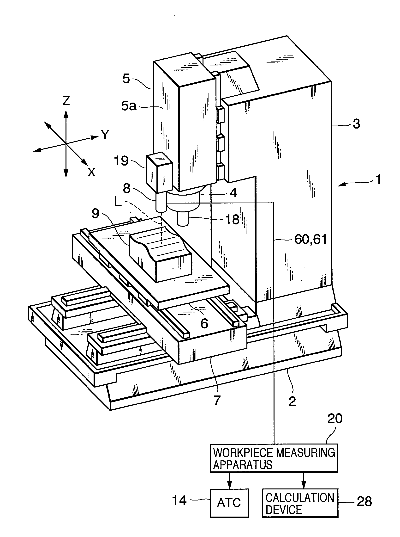
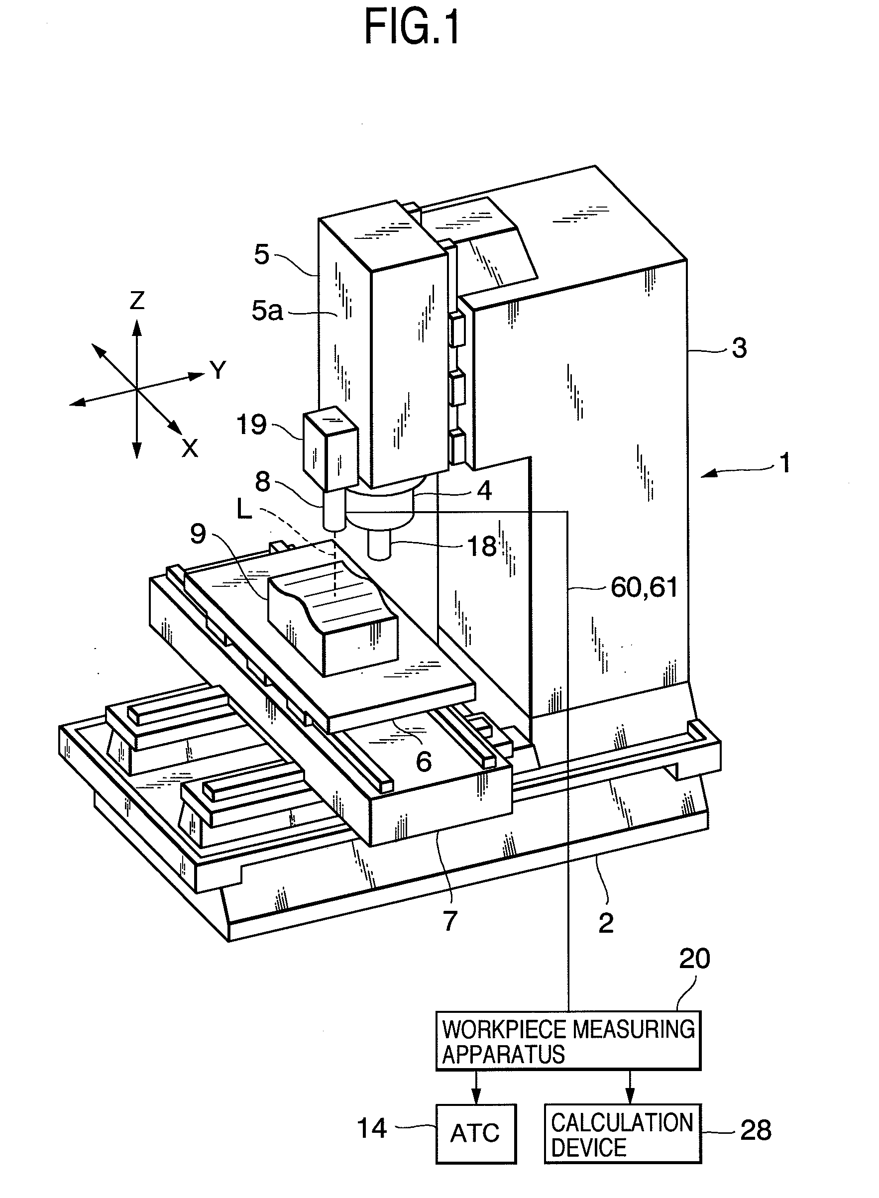
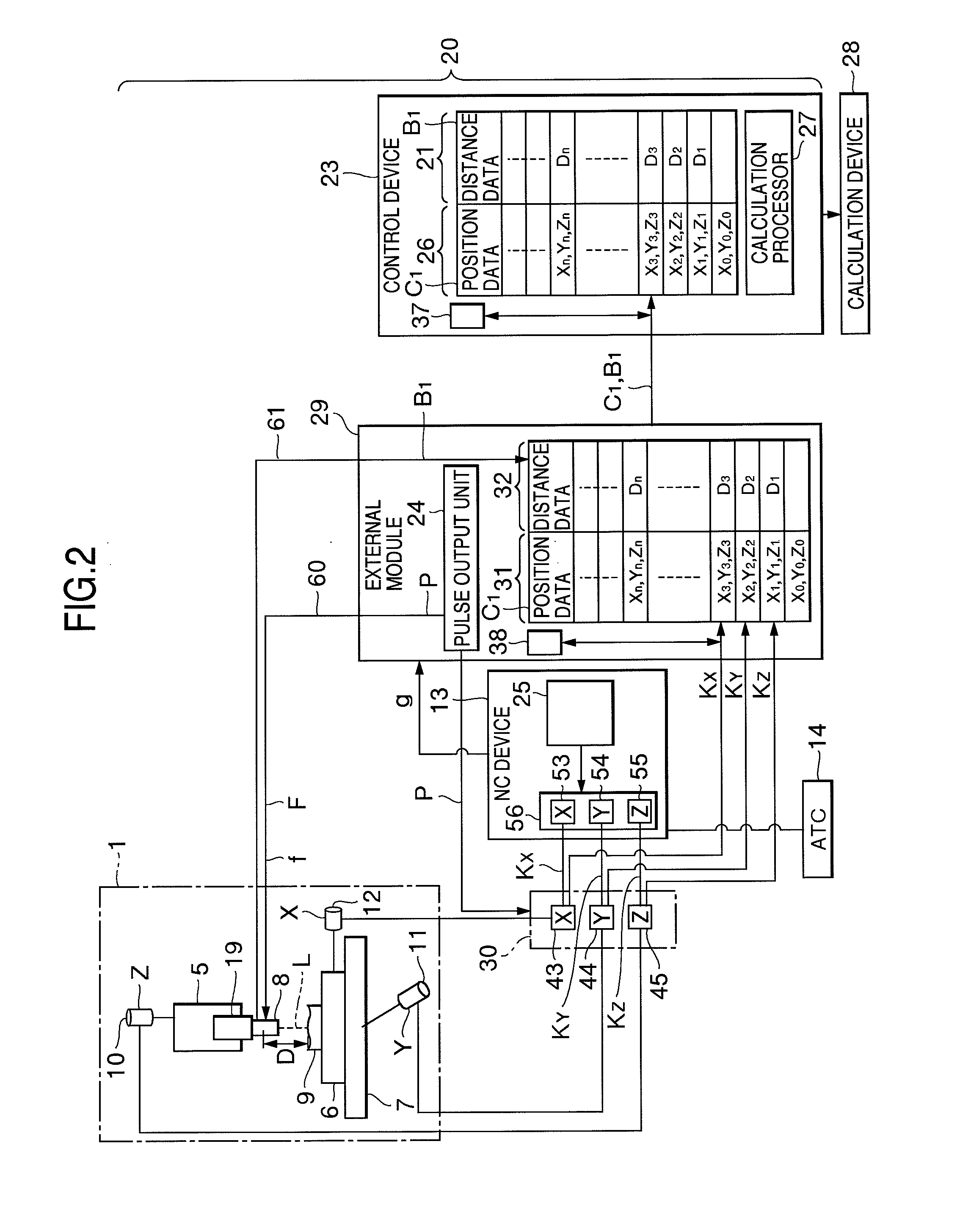
[0042]FIG. 1 is a perspective view of a machine tool equipped with a workpiece measuring apparatus having a wired measuring head, FIG. 2 outlines the configuration of the workpiece measuring apparatus illustrated in FIG. 1, FIG. 3 is an explanatory view illustrating a situation of measuring the workpiece and FIG. 4 lists the data input to a control device and results of calculation thereof.

[0043]As illustrated in FIGS. 1 and 2, a vertical machining center is illustrated as a machine tool 1 in the present embodiment. The machine tool 1 has a bed 2 installed on the floor surface, a column 3 mounted on the bed 2, a spindle head 5 having a main spindle 4, and a saddle 7 having a table 6. The machine tool 1 is controlled by an NC device (Numerical Control device) 13...

second embodiment

[0157]FIG. 5 outlines a configuration of a workpiece measuring apparatus 20a on a machine tool 101 having a wireless measuring head 8a according in a second embodiment of the present invention. Here, components identical or equivalent to those of the first embodiment are provided with identical reference numerals and description thereof is omitted.

[0158]As illustrated in FIG. 5, the measuring apparatus 20a has the wireless measuring head 8a which measures the workpiece 9. The measuring head 8a is attached to the spindle head 5, which is a movable unit moving relative to the workpiece 9, in a machining area of the machine tool 101 controlled by the NC device 13, and detects the position and shape of the workpiece 9. The measuring head 8a is a displacement sensor capable of measuring the distance D to the workpiece 9 and of outputting the distance data B1.

[0159]The measuring apparatus 20a has the control device 23, which controls the apparatus 20a, and the module 29.

[0160]The module 2...


PUM


Abstract

A workpiece measuring apparatus has an external module provided outside an NC device to acquire position data of one or more movable axes of a movable unit having a measuring head attached thereto. The position data of the measuring head is acquired at the same time interval as that for the distance measurement by the measuring head. The position of the workpiece is acquired by calculation from the acquired distance measurement data and the position data of the measuring head. The continuous shape of the workpiece can be measured by performing continuous measurement while moving the measuring head. Therefore, no modification or change is required such as adding a new function to the NC device. In addition, the present invention is applicable to any machine tool equipped with an NC device of any configuration, without being restricted by constraints of the NC device.

Description

BACKGROUND OF THE INVENTION[0001]1. Field of the Invention[0002]The present invention relates to an apparatus for and a method of measuring a workpiece on a machine tool, wherein the workpiece is measured with a wired or wireless measuring head attached to a movable unit moving relatively to the workpiece in a machining area of the machine tool.[0003]2. Description of the Related Art[0004]For a machine tool such as a machining center, there have been proposed techniques of measuring the shape of the surface of a workpiece attached to the machine tool without removing the workpiece from the machine tool after machining. For example, a workpiece inspection system for a machine tool is described in Japanese published patent application JP2007-518579 (corresponding to WO 2005 / 065884).[0005]This work inspection system has a probe (corresponding to the measuring head of the present invention) mounted on a main spindle of the machine tool. The data measured, when a needle of the probe cont...

Claims


Application Information

Patent Timeline
Patent Type & Authority Applications(United States)
IPC IPC(8): G05B19/401
CPCB23Q17/22B23Q17/20Y02P90/02
Inventor NISHIKAWA, SHIZUOUENO, KENICHIROMORITA, HISAYOSHIONO, KATSUHIKO
Owner DMG MORI CO LTD
Why Eureka
Try Eureka