Fuel feed device for aviation engine

a technology for aviation engines and fuel feed devices, which is applied in the direction of turbine/propulsion fuel valves, functional valve types, machines/engines, etc., can solve the problems of excessive rotation speed of turbine shafts, rotor disks mounted on shafts that burst, and the use of jet pumps in association with an overspeed protection unit operating as described above raises difficulties

Active Publication Date: 2011-10-20
SN DETUDE & DE CONSTR DE MOTEURS DAVIATION S N E C M A
View PDF3 Cites 18 Cited by
  • Summary
  • Abstract
  • Description
  • Claims
  • Application Information

AI Technical Summary

Benefits of technology

[0009]The present invention aims to provide a fuel feed device equipped with an FMU associated with an overspeed protection unit and coupled to a jet pump which guarantees shutoff of fuel feed in the event that over...

Problems solved by technology

In an aviation gas turbine engine, excessive rotation speed of a turbine shaft can have severe consequences, to wit causing the rotor disks mounted on the shaft to burst.
It has become apparent that such a use of a jet pump in association with an overspeed protection unit operating as described above raises a difficulty.
As it happens, for the contribution from the jet pump to be effective, the nozzle of the primary intake of the jet pump must have a rather small flow area, which results in a considerable restriction in the bypass fuel return circuit.
In the event of full opening of the bypass valve caused by detection of an overspeed, the presenc...

Method used


Image

  • Fuel feed device for aviation engine
  • Fuel feed device for aviation engine
  • Fuel feed device for aviation engine

Examples


Embodiment Construction

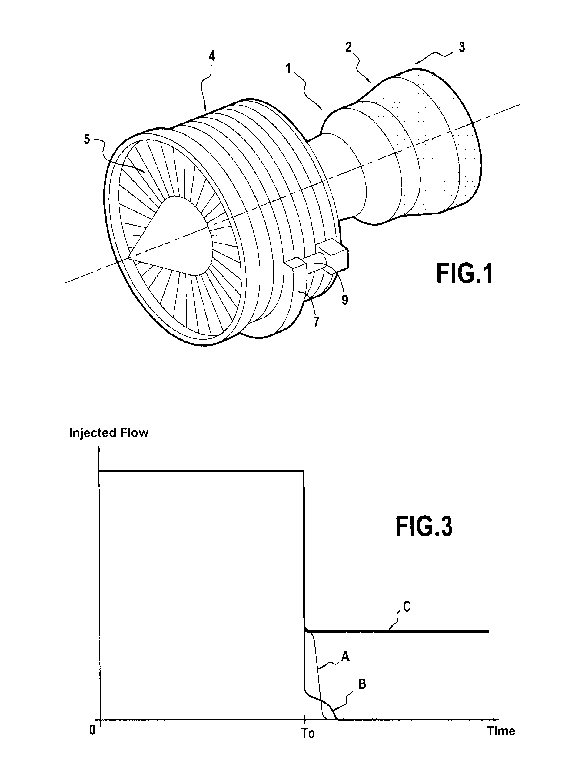
[0023]Embodiments of the invention will be described hereafter within the framework of an application to a twin-spool gas turbine engine for airplane propulsion such as that shown very schematically in FIG. 1, the invention being applicable, however, to other airplane engines, for example single spool gas turbine engines or those with more than two spools.

[0024]The engine in FIG. 1 includes a combustion chamber 1, the combustion gases issuing from chamber 1 driving a high-pressure (HP) turbine 2 and a low-pressure (LP) turbine 3. The HP turbine 2 is coupled by a HP shaft to a HP compressor 4 feeding air under pressure to the combustion chamber while the LP turbine 3 is coupled to a blower 3 at the engine intake by means of a LP shaft coaxial with the HP shaft.

[0025]An accessory gearbox or AGB 7 is connected by a mechanical power take-off to a turbine shaft and includes a gear assembly for driving various accessories such as pumps, one or more starter / generators, one or more permanen...


PUM


Abstract

A jet pump (14) is inserted between the low-pressure pump and a high-pressure fuel pump (16). A fuel metering unit (20) includes a metering valve (22) which delivers a regulated fuel flow to a feed line (30), and a bypass valve (24) which diverts to a primary intake (14a) of the jet pump the excess fuel flow supplied by the high-pressure pump. An overspeed protection unit (50) includes a control element (54) of the bypass valve (24) which causes said to fully open in the event of an overspeed of the engine. A shutoff and pressurization checkvalve (42) is mounted on the feed line and controlled by a servo-valve (44) having a high-pressure port (44a) brought to the high fuel pressure, a low-pressure port brought to the pressure of the primary intake (14a) of the jet pump and an output setting the pressure in a control chamber (42a) of the shutoff valve (42) to a value between those prevailing at the high pressure and low pressure ports. In the event of overspeed, the restriction imposed by the jet pump causes a pressure rise at the primary intake of the jet pump, hence a pressure rise in the control chamber of the shutoff valve (42), favoring the closing thereof.

Description

BACKGROUND OF THE INVENTION[0001]The invention relates to a fuel feed device for an aviation engine, more particularly for a gas turbine propulsion engine for airplanes.[0002]In known fashion, a fuel feed device for a combustion chamber of a gas turbine propulsion engine for airplanes includes a pumping unit providing fuel under high pressure to a fuel metering unit or FMU, which delivers a regulated flow of fuel to a fuel feed line of the combustion chamber.[0003]The pumping unit typically includes a high-pressure fuel pump which supplies the FMU and which receives fuel from a low-pressure fuel pump connected to a fuel reservoir. The high-pressure pump is customarily driven by coupling to a gear in a mechanical gearbox or accessory gearbox (AGB) connected by a power takeoff to a turbine shaft.[0004]The FMU typically includes a variable-position metering valve controlled by an engine control computer or engine control unit (ECU) according to the fuel delivery desired in the feed lin...

Claims


Application Information

Patent Timeline
IPC IPC(8): F16K15/00
CPCF01D21/02F05D2260/601F02C9/263F02C7/232Y10T137/7837F02C7/236
Inventor DORE, BASTIENPORA, LOIC
Owner SN DETUDE & DE CONSTR DE MOTEURS DAVIATION S N E C M A
Why Eureka
Try Eureka