Portable wave-swash & coastal-wind energy harvester

a technology of energy harvester and portability, which is applied in the direction of reciprocating combination engines, electric generator control, greenhouse gas reduction, etc., can solve the problems of not being able to operate in the wave-swash zone, the technology of capturing economic energy from these sources remains a technological challenge, and the water wheel will not work, etc., to achieve the effect of stable operation location, maneuverability in water, and portability of the uni

Inactive Publication Date: 2011-10-20
JOSEPH ERAT S
View PDF3 Cites 31 Cited by
  • Summary
  • Abstract
  • Description
  • Claims
  • Application Information

AI Technical Summary

Problems solved by technology

The description states, “The turntable is rotated on bearings over a fixed-horizontal base plate, until the set-up is facing the wind and waves directly to the best advantage.” One of the deficiencies of the apparatus is due to the fact that the directions of wind and wave do not necessarily match, and while the horizontal-axis wind wheel will not work unless its orientation changes to face the wind, a water wheel will not work unless it faces water flow.
It is not designed for operation in the wave-swash zone.
None of the above mentioned patents includes any device to assist in the retention of angular momentum for maintaining sustained rotational energy.
Despite the fact that abundant energy is available in wind and in sea waves, capturing of this energy economically from these sources remains a technological challenge.
One of the major drawbacks of wind mill technology lies in its very low capacity factor—the ratio of the power actually produced to the power that would have been produced if the turbines operated 100% of the time.
Standard wind mills are huge in size, and are economically not feasible.
One of the difficulties faced by wave turbine technology is due to the periodic nature of the occurrence of the waves and the resulting variability of torque produced by wave turbines.

Method used


Image

  • Portable wave-swash & coastal-wind energy harvester
  • Portable wave-swash & coastal-wind energy harvester
  • Portable wave-swash & coastal-wind energy harvester

Examples


Embodiment Construction

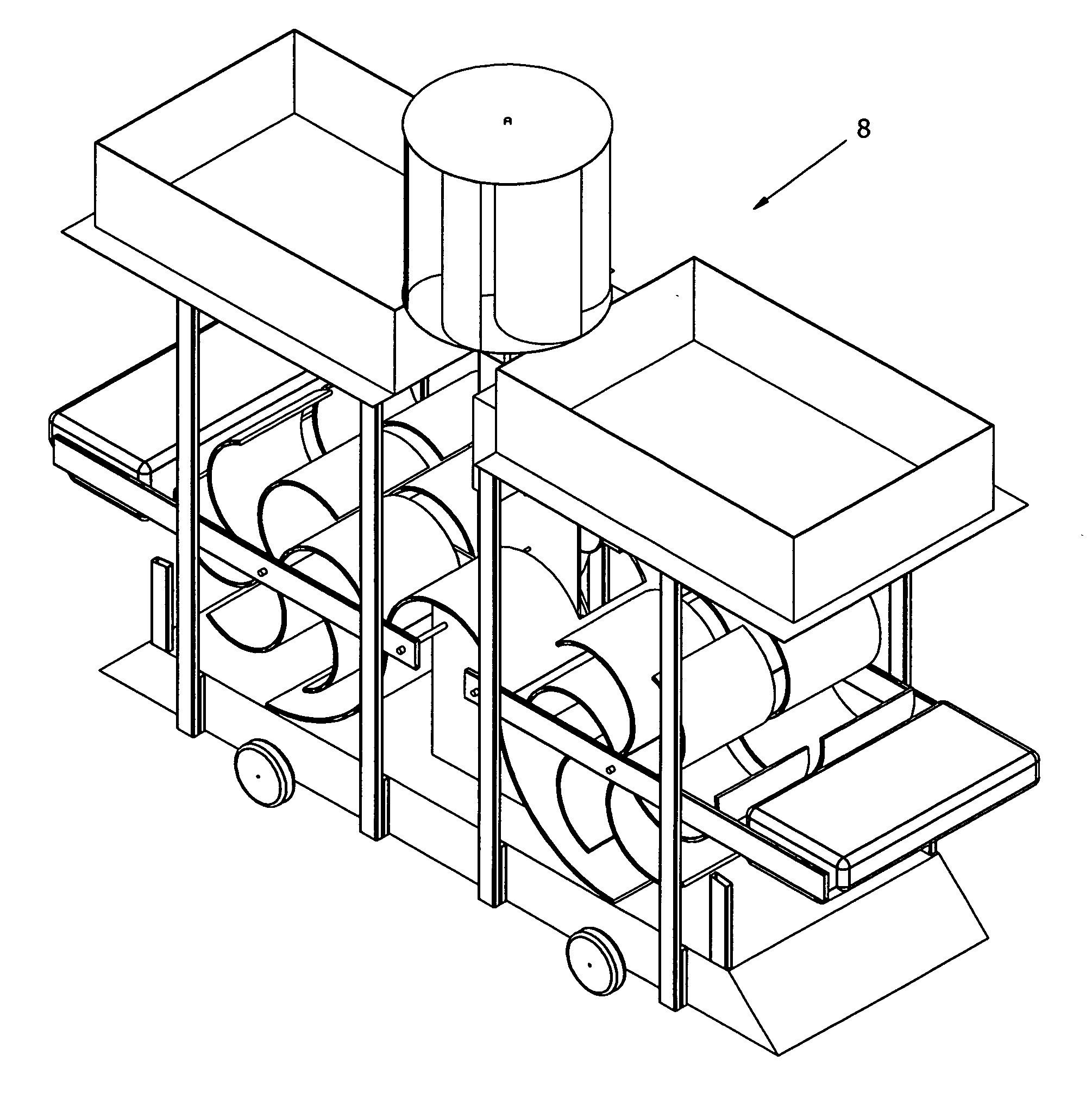
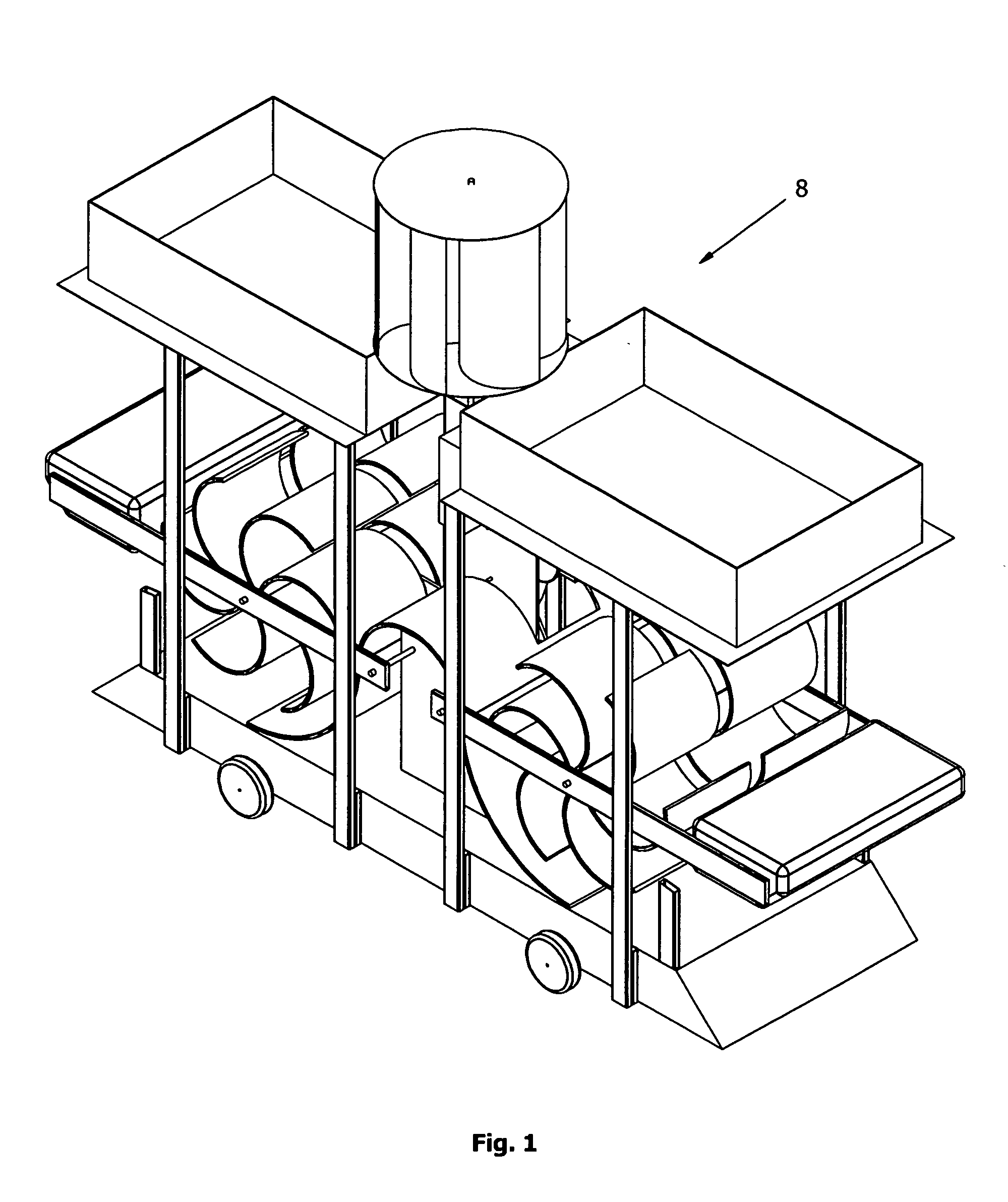
[0062]FIG. 1 is an isometric front view of the portable wave-swash & coastal-wind energy harvester invention 8.

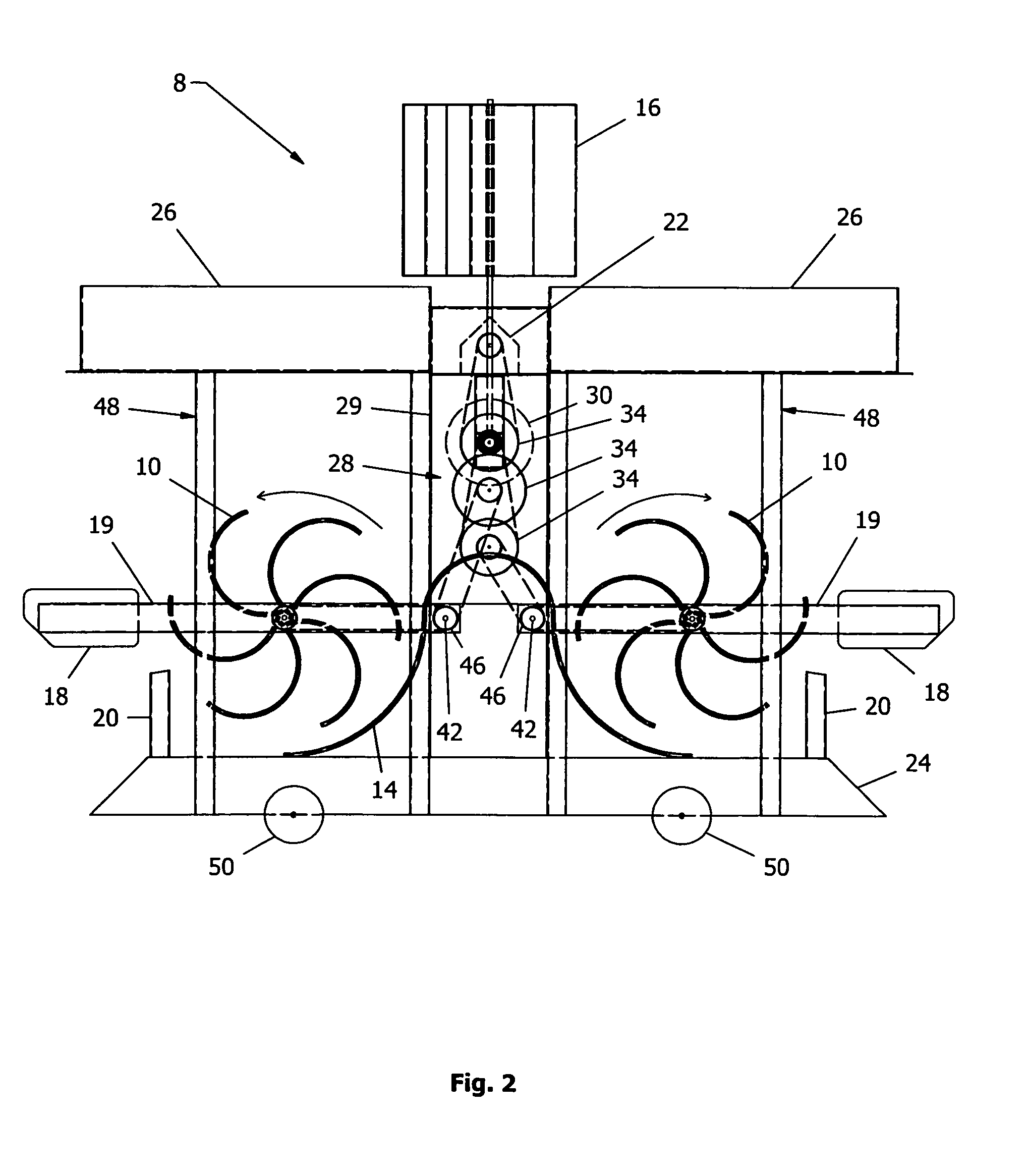
[0063]FIG. 2 is a right elevation view of the portable wave-swash & coastal-wind energy harvester invention 8. Included elements: wave turbines 10, wave-turbine surround covers 14, wind turbines 16, wave floats 18, wave-float levers 19, float restraints 20, alternator 22, buoyancy chamber 24, stabilization tanks 26, rotational transmission-system 28, transmission-system cover 29, flywheels 30, large sprockets 34, one-way clutches 42, bearings 46, frame 48, and wheels 50.

[0064]FIG. 3 is a front elevation view of the portable wave-swash & coastal-wind energy harvester invention 8. Included elements: wave turbines 10, wind turbines 16, alternator 22, buoyancy chamber 24, stabilization tanks 26, rotational transmission-system 28, transmission-system cover 29, flywheels 30, axles 32, bevel gears 40, one-way clutches 42, frame 48, and wheels 50.

[0065]FIG. 4 is the top view of the...


PUM


Abstract

In accordance with the present invention, a portable wave-swash & coastal-wind energy harvester, placed on a sea coast in swash zone captures energy contained in coastal waves and in coastal-wind through the utilization of wave turbines, wind turbines, and wave floats. Wave-float levers carrying wave floats and wave turbines, swing and maintain lower halves of wave turbines below water always. A gear system with one-way clutches transmits torque to an alternator to generate electricity. Flywheels maintain steady rotation of alternator shaft. A buoyancy chamber at the bottom produces reduction of weight of the unit when buoyancy chamber is emptied of water, and thereby enhances maneuverability of unit in water. Stabilization tanks at the top when filled with water provide extra weight and stability of the unit in its operating location. Units linked together in an energy farm combine their energy while forming a seawall-like barrier offering protection against coastal erosion.

Description

RELATED APPLICATIONS[0001]The present application is a continuation-in-part application of U.S. patent application Ser. No. 12 / 799,164, filed Apr. 20, 2010 for PORTABLE WAVE-SWASH & COASTAL-WIND ENERGY HARVESTER, by Erat S. Joseph, included by reference herein and for which benefit of the priority date is hereby claimed.FIELD OF THE INVENTION[0002]The present invention relates to the simultaneous capturing of the energy contained in sea waves and in wind.BACKGROUND OF THE INVENTIONBackground[0003]The following is a tabulation of some prior art that presently appears relevant U.S. patentsPat. No.Date of PatentPatentee3,687,567Aug. 29, 1972William C. Lininger4,319,454Mar. 16, 1982Louis V. Lucia4,392,060Jul. 5, 1983Jessie T. Ivy4,719,754Jan. 19, 1988Kochi Nishikawa5,005,357Apr. 9, 1991Mansel F. Fox5,244,359Sep. 14, 1993David M. Slonim5,549,445Aug. 27, 1996Edward J. Schremp6,109,863Aug. 29, 2000Larry D. Milliken6,269,636 B1Aug. 7, 2001Constantinos Hatzilakos6,559,552 B1May 6, 2003Siu Kw...

Claims


Application Information

Patent Timeline
Patent Type & Authority Applications(United States)
IPC IPC(8): F03B13/18F03B13/22F03D3/00
CPCF03B13/144F03B13/183Y02E10/72F05B2260/421Y02E10/38F03D9/008F03D9/12Y02E60/16F03D15/10F03D9/25Y02E10/30Y02E70/30
Inventor JOSEPH, ERAT S.
Owner JOSEPH ERAT S
Why Eureka
Try Eureka