Energy harvester utilizing external magnetic field

a technology of energy harvester and magnetic field, which is applied in the direction of magnetic property measurement, instruments, inductance, etc., can solve the problems of unsatisfactory damping and noise generation levels, and achieve the effect of small and ligh

Inactive Publication Date: 2010-10-05
FERRO SOLUTIONS
View PDF21 Cites 44 Cited by
  • Summary
  • Abstract
  • Description
  • Claims
  • Application Information

AI Technical Summary

Benefits of technology

[0007]In accordance with various embodiments of the present invention, an apparatus is provided for harvesting energy from the environment or other remote sources and converting it to useful electrical energy. The harvester does not contain a permanent magnet or other local field source but instead relies on

Problems solved by technology

While each of the known types of vibrational energy harvesters have different advantages, they also have drawbacks such as: the need for heavy, powerful permanent magnets (in the case of inductive energy harvesters) to produce a sufficiently large flux density; an auxiliary source of power, such as a battery (in the case of capacitive harvesters); the need for large vibration frequencies and/or a heavy iner

Method used


Image

  • Energy harvester utilizing external magnetic field
  • Energy harvester utilizing external magnetic field
  • Energy harvester utilizing external magnetic field

Examples


first embodiment

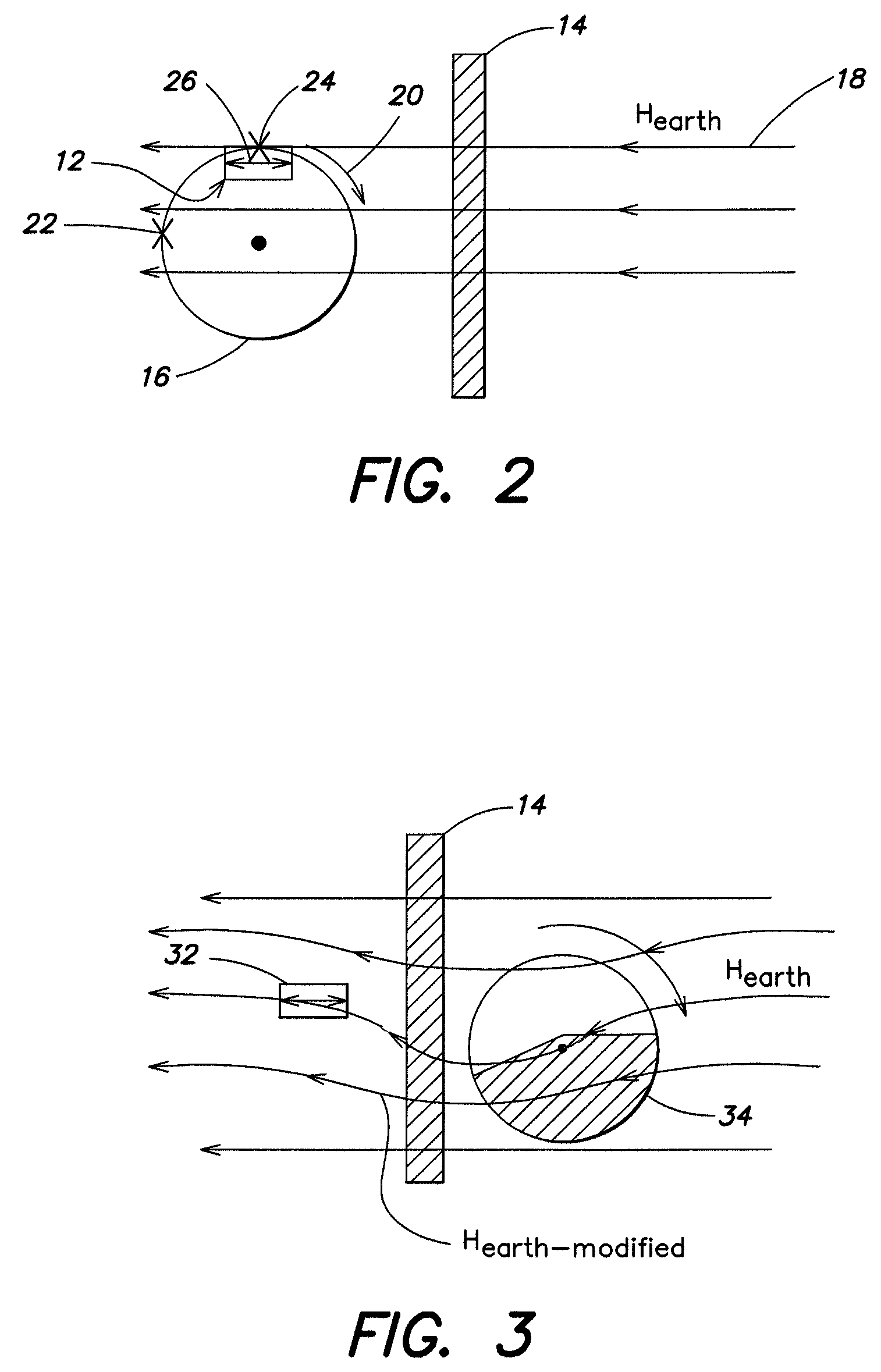
[0069]FIG. 2 illustrates an energy harvester device according to the invention, wherein a static external magnetic field, here Hearth (the earth's magnetic field), acts at a distance (or through a non-magnetic barrier) on a sensor whose orientation in the field changes with time. Thus, the flux density in the sensor is altered by changes in the physical orientation of the sensor with respect to the direction of the earth's field (or other substantially static field). FIG. 2 illustrates this with a non-magnetic barrier 14 separating the energy harvester 12 on the left, attached to a moving object (rotating machinery part 16), from the source of external field 18 on the right. The arrow 26 extending across the width of sensor 12 represents the plane of the magnetization vector M. The arrow 20 illustrates rotation of sensor 12 from a first position 22 (labeled X) to a second position 24 (labeled X′). Alternatively, the sensor can be attached to a rotating part on a vehicle, a door, or ...

second embodiment

[0070]the invention is shown in FIG. 3, wherein a changing external field, Hearth-modified, acts at a distance (or through a non-magnetic barrier) on a stationary sensor 32. Here the orientation of the field at the sensor location changes with time. In FIG. 3, a moving magnetic object (rotating disk 34) in the path of the earth's ambient field causes a change in that field, and this changing field (Hearth-modified) then reaches (acts on) the static sensor 32.

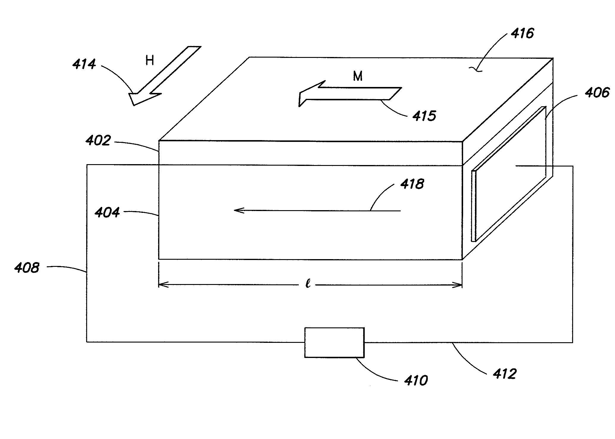
[0071]In a further alternative embodiment, shown in FIG. 4, a permanent magnet 42 is affixed to a rotating or moving object 44 remote from the sensor 48. The change in position of the magnet 42 relative to the stationary sensor 48 causes a changing field (see field lines 46 of Hext) that acts on the static sensor 48. Arrow 45 illustrates rotation of the magnet to a second position (shaded area 42′ at the bottom of rotating disk 44) and the changing field as dashed lines 46′. Other sources of changing or alternating magnetic fiel...


PUM


Abstract

Apparatus and method for harvesting energy from the environment and/or other external sources and converting it to useful electrical energy. The harvester does not contain a permanent magnet or other local field source but instead relies on the earth's magnetic field of another source of a magnetic field that is external to the sensing device. One advantage of these new harvesters is that they can be made smaller and lighter than energy harvesters that contain a magnet and/or an inertial mass.

Description

RELATED APPLICATIONS[0001]This application claims the benefit of priority to U.S. Provisional Application No. 60 / 758,042 filed Jan. 11, 2006 entitled “Novel Energy Harvester Without Moving Parts” by J. Huang et al., U.S. Provisional Application No. 60 / 790,921 filed Apr. 11, 2006 entitled “Wireless Transfer of Electrical Power From Outside a Body to Inside a Body” by J. Huang et al., and U.S. Ser. No. 10 / 730,355 filed 8 Dec. 2003 entitled “High Sensitivity, Passive Magnetic Field Sensor and Method of Manufacture” by J. Huang et al., which claims priority to U.S. Provisional Application No. 60 / 431,487 filed 9 Dec. 2002, the disclosures of which are hereby incorporated by reference in their entirety.FIELD OF THE INVENTION[0002]This invention relates to apparatus and methods for harvesting energy from the environment and other sources external to the harvester and converting it to useful electrical energy.BACKGROUND OF THE INVENTION[0003]Energy harvesters are known that convert vibratio...

Claims


Application Information

Patent Timeline
IPC IPC(8): G01R33/02G01R29/22
CPCG01R33/18H01L41/00H10N35/00H10N30/00
Inventor HUANG, JIANKANGO'HANDLEY, ROBERT C.BONO, DAVID C.
Owner FERRO SOLUTIONS
Why Eureka
Try Eureka