Wind turbine

a wind turbine and wind power technology, applied in the direction of electric generator control, machines/engines, mechanical equipment, etc., can solve the problems of enlargement of the total weight and complicated assembly and transportation of the wind turbine, and achieve the effects of reducing the total weight, convenient transportation, and compact structur

Inactive Publication Date: 2011-10-20
SIEMENS AG
View PDF8 Cites 17 Cited by
  • Summary
  • Abstract
  • Description
  • Claims
  • Application Information

AI Technical Summary

Benefits of technology

[0007]It is an object of the invention to provide a wind turbine with a reduced total weight, which is more compact so that transportation is made easier.

Problems solved by technology

The big diameter of the direct drive generator caused the enlargement of the total weight and complicated the assembly and transportation of the wind turbine.

Method used


Image

  • Wind turbine
  • Wind turbine
  • Wind turbine

Examples


Embodiment Construction

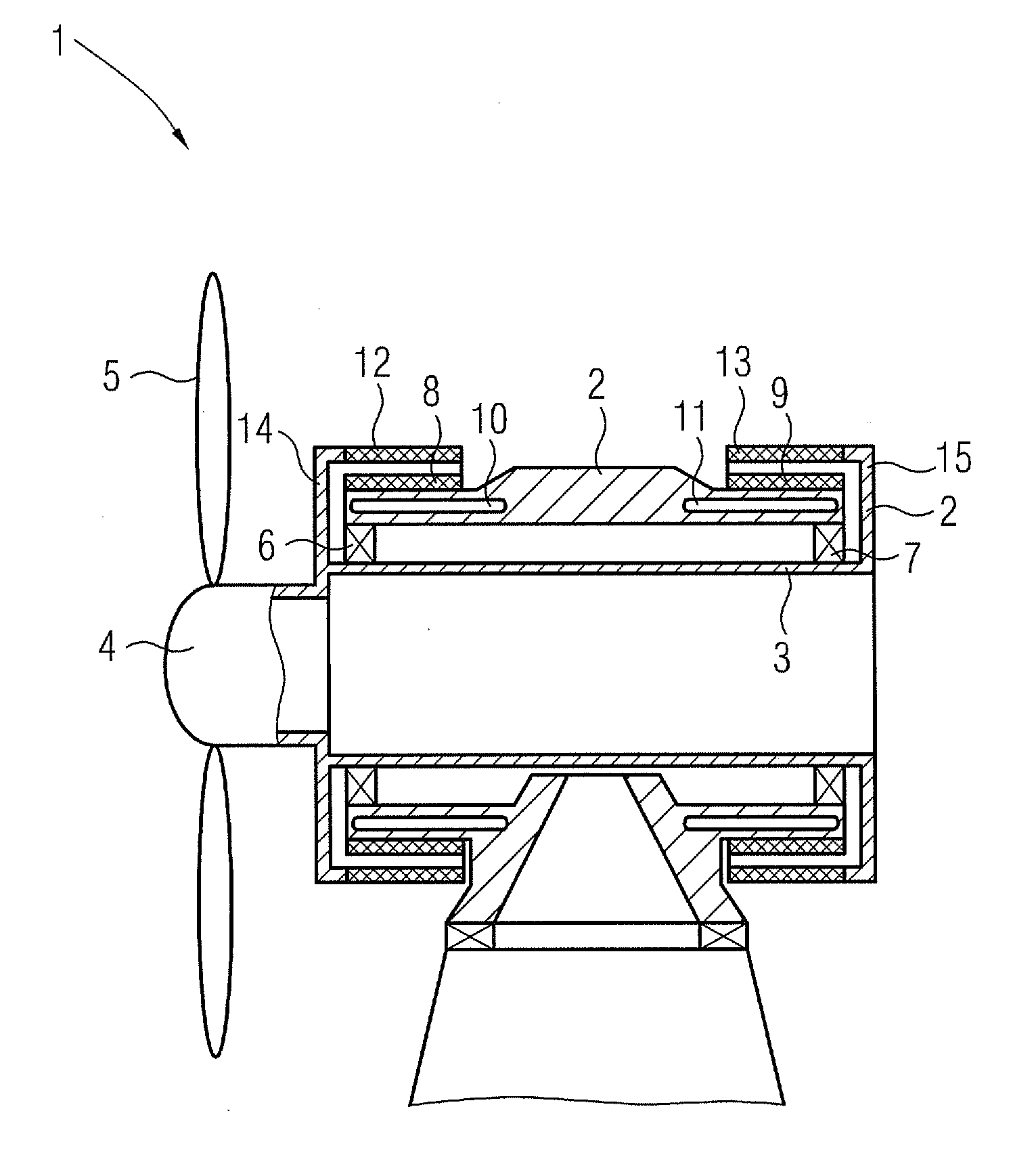
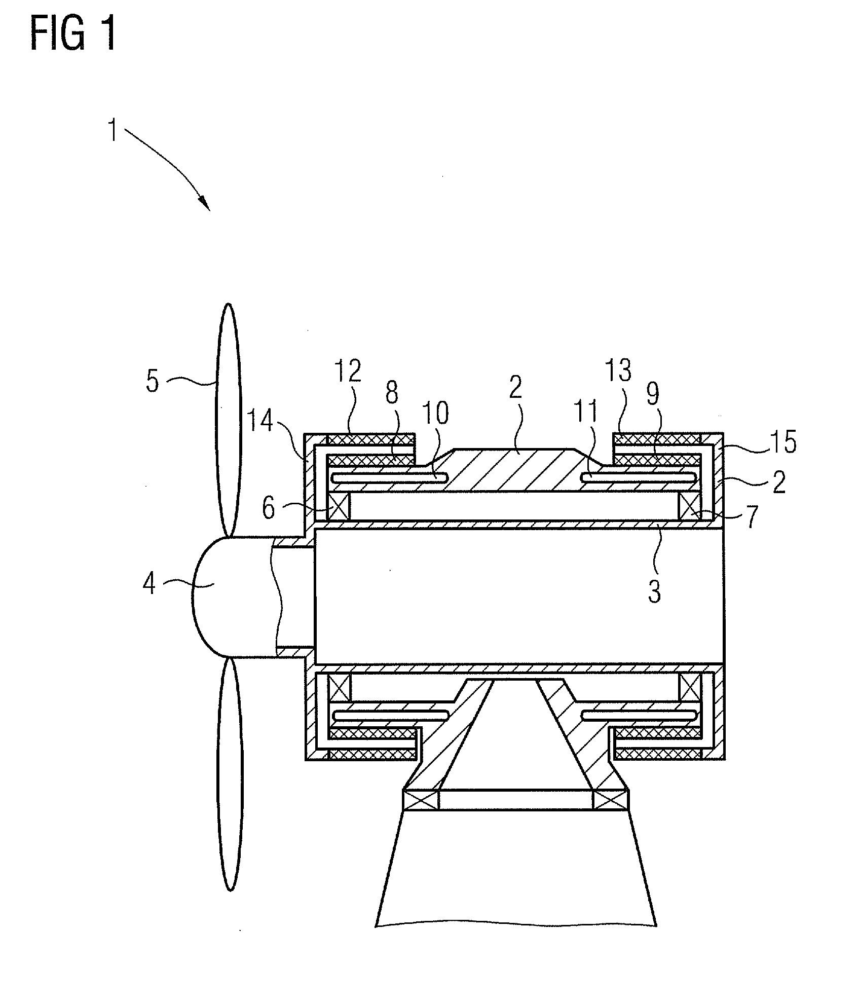
[0022]FIG. 1 shows a wind turbine in a sectional view, comprising a housing 2 containing a hollow main shaft 3 which can be rotated. The housing 2 is mounted on a tower. A hub 4 is connected to the main shaft 3, blades 5 are mounted on the hub 4. When wind passes over the blades 5 the hub 4 and the main shaft 3 are rotated. A bearing arrangement comprising a fixed bearing 6 and a floating bearing 7 is arranged within the housing 2. The fixed bearing 6 is installed as a double row spherical roller bearing or a double row tapered roller bearing, the floating bearing 7 is formed as a toroidial roller bearing or a cylindrical roller bearing.

[0023]A first stator 8 is mounted on the blade side of the wind turbine 1, a second stator 9 is mounted on the opposite side. Both stators 8, 9 are faulted as rings which are arranged at the outer side of the housing 2. A water cooling system 11 is assigned to each stator 8, 9.

[0024]External rotors 12, 13 are arranged on flanges 14, 15, which are con...


PUM


Abstract

A wind turbine is provided. The wind turbine includes a housing containing a main shaft a first generator with a stator and a rotor, and a second generator with a stator and a rotor. The first generator is mounted on a blade side of the main shaft whereas the second generator is mounted on the opposite side of the main shaft. The stator of the first generator is encircled by the rotor of the first generator and the stator of the second generator is encircled by the rotor of the second generator.

Description

CROSS REFERENCE TO RELATED APPLICATIONS[0001]This application claims priority of European Patent Office application No. 10004077.3 EP filed Apr. 16, 2010, which is incorporated by reference herein in its entirety.FIELD OF INVENTION[0002]The present invention relates to a wind turbine, comprising a housing containing a main shaft, at least a first generator with a stator and a rotor, mounted on a blade side of the main shaft and a second generator with a stator and a rotor, mounted on the opposite side of the main shaft.BACKGROUND OF INVENTION[0003]Wind turbines include blades mounted on a hub attached to a rotor that rotates when wind passes over the blades. The rotation of the rotor is used to drive an electrical generator. Typically the rotor carries conductor windings or coils that face magnetic field generators on a stator such that there is relative motion between the coils and the magnetic field generators in order to produce electricity.[0004]In recent years the engine power ...

Claims


Application Information

Patent Timeline
Patent Type & Authority Applications(United States)
IPC IPC(8): F03D9/00H02K9/19
CPCF03D9/002Y02E10/725H02K7/1838F05B2220/7066F03D9/25Y02E10/728Y02E10/72F03D80/70F03D13/20
Inventor VENTZKE, KLAUS
Owner SIEMENS AG
Why Eureka
Try Eureka