Sub sampling electrical power conversion

a sub-sampling and electrical power technology, applied in pulse generators, pulse generation by energy-accumulating elements, pulse techniques, etc., can solve problems such as energy loss, and achieve the effect of low cost components

Active Publication Date: 2011-10-20
TELEFON AB LM ERICSSON (PUBL)
View PDF5 Cites 8 Cited by
  • Summary
  • Abstract
  • Description
  • Claims
  • Application Information

AI Technical Summary

Benefits of technology

[0027]The solution for power conversion according to the present invention as shown in in this document and in the claims has the advanta...

Problems solved by technology

Evidently due to resonator...

Method used


Image

  • Sub sampling electrical power conversion
  • Sub sampling electrical power conversion
  • Sub sampling electrical power conversion

Examples


Embodiment Construction

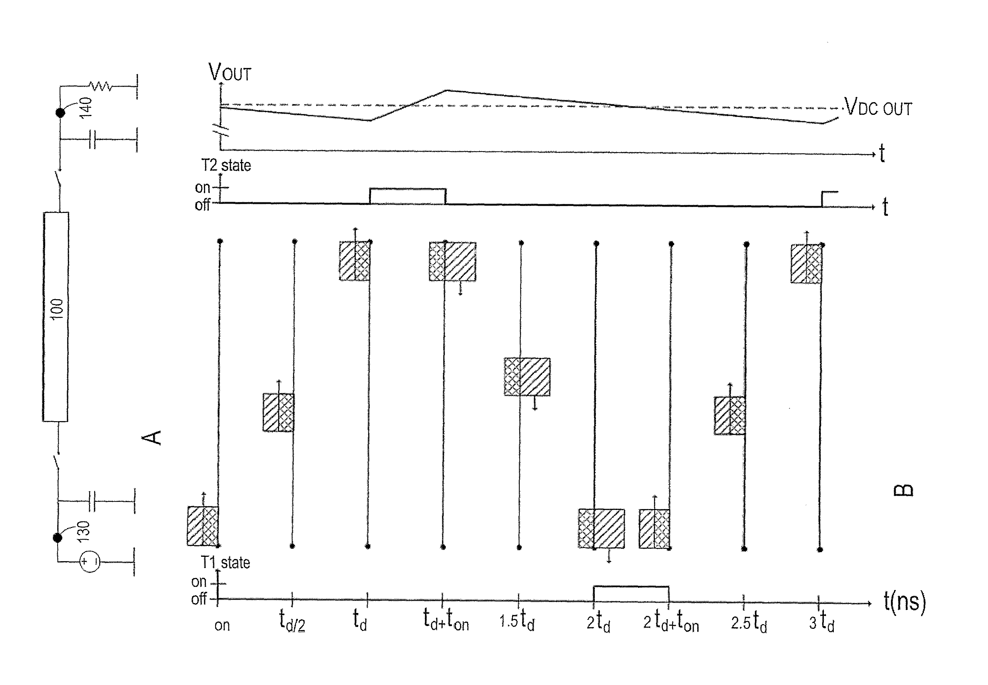
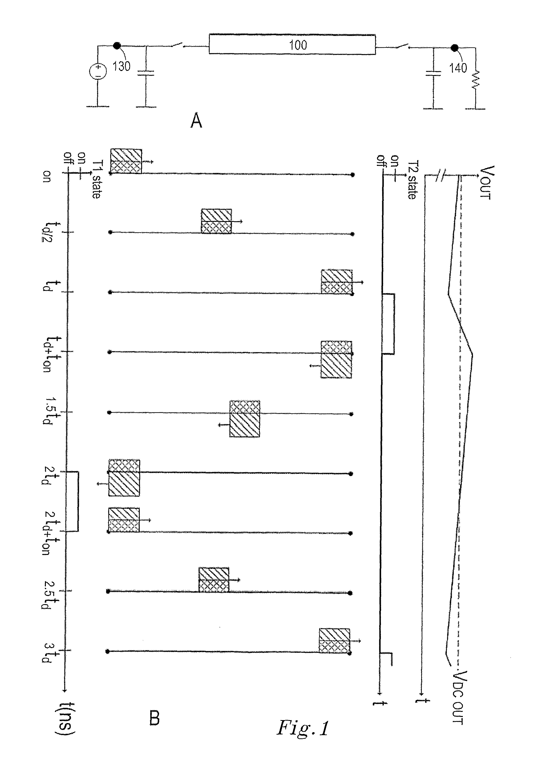
[0062]The present invention relates to different electrical power conversions of electrical energy in an electrical circuit using a wave propagation medium, such as a transmission (delay) line or similar electrical transmission delay paths, such as a lumped transmission line, a strip line, a micro strip, a PCB track, and so on, and properties of impedance mismatch in relation to the transmission line / path. When an electrical wave is transmitted in a transmission line / path and encounters an impedance mismatch at least part of the electrical wave is reflected back into the transmission line / path. This is illustrated in FIG. 1A, where a step-down DC / DC circuit is shown. In the figure the input voltage VDC IN is stepped down to voltage VDC OUT. The operating principle of the circuit in FIG. 1A will be explained later.

[0063]In this embodiment, T1 and T2 are transistor switches and the transmission line 100 is used as an energy storage medium. Capacitor CIN is used as a low impedance sour...


PUM


Abstract

The present invention relates to a solution for electrical power conversion using a first gate (202, 302) for starting an electrical wave in a wave propagating medium (205, 306) acting as a transmission delay where an electrical wave propagates and due to reflections in the propagating medium a resulting wave builds up and is transferred to an output for delivering a power amplifier, DC/DC converter or similar function and the output is controlled using a second gate (204, 304).

Description

TECHNICAL FIELD[0001]The present invention relates to a solution for electrical power conversion using an electrical transmission line, plane or volume.BACKGROUND OF THE INVENTION[0002]Several different solutions exist in order to provide a suitable voltage to an electrical circuit, both as supply voltage and as voltage input to the circuit. Often a DC / DC converter is used to convert a fixed level to another level (step up or step down). Similarly AC / CD converters are used to convert an AC voltage to DC voltage at a certain level.[0003]It is known to use an electrical transmission line for generating electrical pulses of high voltages or for DC / DC voltage conversion in a switching manner using short pulses traveling in the transmission line and synchronizing switches to perform the DC / DC voltage conversion. This is known for example through WO2008 / 051119.[0004]The use of conventional DC / DC voltage converters can sometimes be problematic due to response times and cost considerations....

Claims


Application Information

Patent Timeline
IPC IPC(8): H03K3/02
CPCH02M3/158H03F1/0211H03K3/86H03K3/53H03F3/60
Inventor SANDER, SVERKER
Owner TELEFON AB LM ERICSSON (PUBL)
Why Eureka
Try Eureka