Liquid crystal panel and liquid crystal display device

a liquid crystal display and liquid crystal panel technology, applied in the field of liquid crystal panel and liquid crystal display device, can solve the problems inconvenience, and difficulty in completely preventing the entry of moisture into the gap between the substrates of the liquid crystal panel, and achieve the effect of reducing display quality

Inactive Publication Date: 2011-10-20
SHARP KK
View PDF7 Cites 29 Cited by
  • Summary
  • Abstract
  • Description
  • Claims
  • Application Information

AI Technical Summary

Benefits of technology

[0023]Such a liquid crystal display device includes a liquid crystal panel as described above. Therefore, even if moisture in an external atmosphere enters a gap between

Problems solved by technology

For a liquid crystal panel of a liquid crystal display device, it is not preferable that moisture in the atmosphere crosses the sealing portion to enter the liquid crystal layer and further reaches the active area, because this may cause stain (fogging) which is uncomfortable to the viewer and reduce the display quality.
Such an inconvenience is inferred to be caused because the ease of alignment of the liquid cr

Method used


Image

  • Liquid crystal panel and liquid crystal display device
  • Liquid crystal panel and liquid crystal display device
  • Liquid crystal panel and liquid crystal display device

Examples


Embodiment Construction

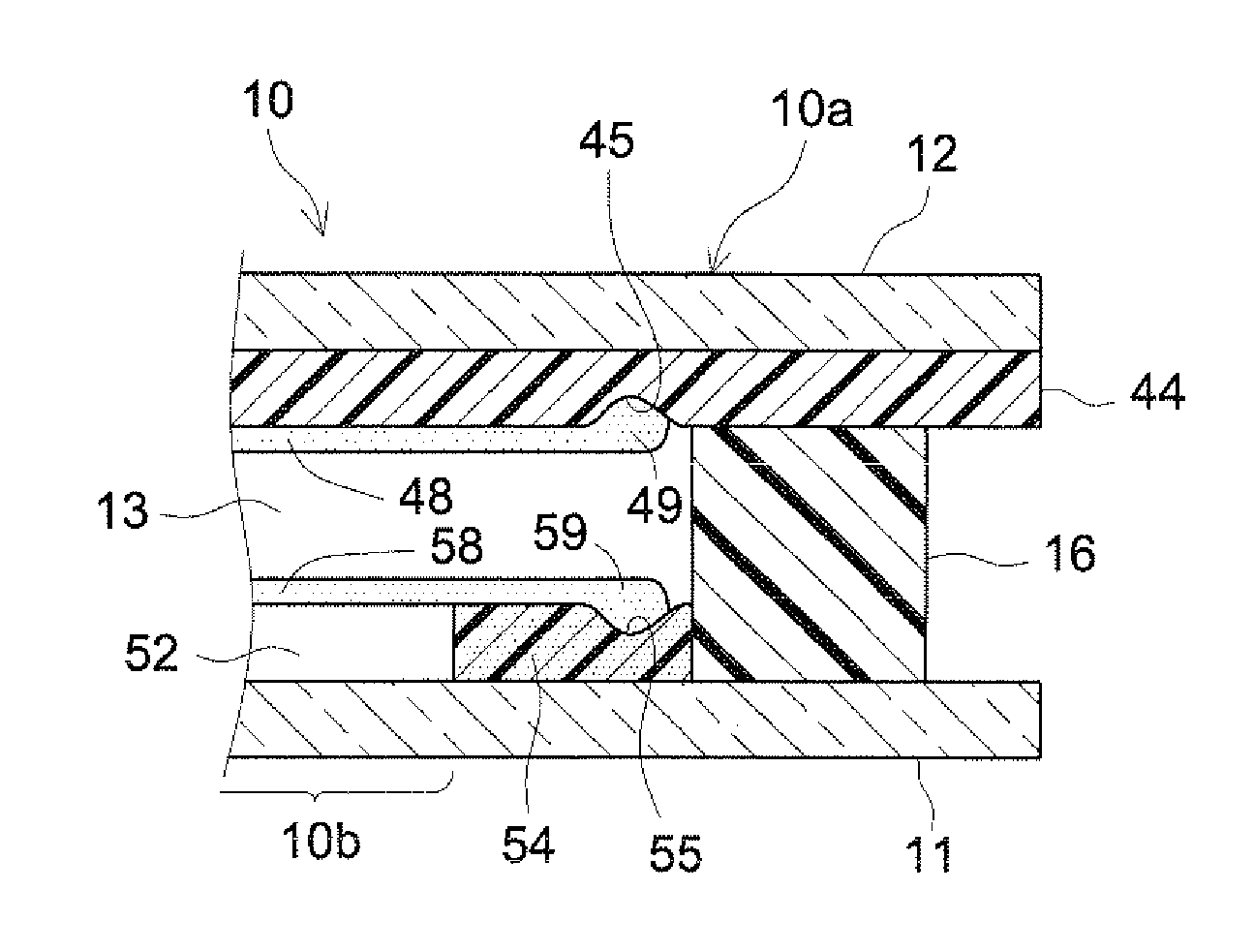
[0033]Hereinafter, some preferable embodiments of the present invention will be described with reference to the drawings. Elements which are other than the elements specifically described in this specification (e.g., the structure of an area including the sealing portion and the vicinity thereof) but are necessary to carry out the present invention (e.g., the method for constructing substrates included in the liquid crystal panel, the structure of a light source included in the liquid crystal display device, the electrical circuit used by the driving system of the light source, etc.) may be understood as being the matter of design choice determined by a person of ordinary skill in the art based on the conventional art. The present invention can be carried out based on the contents disclosed in this specification and the technological common knowledge in the art.

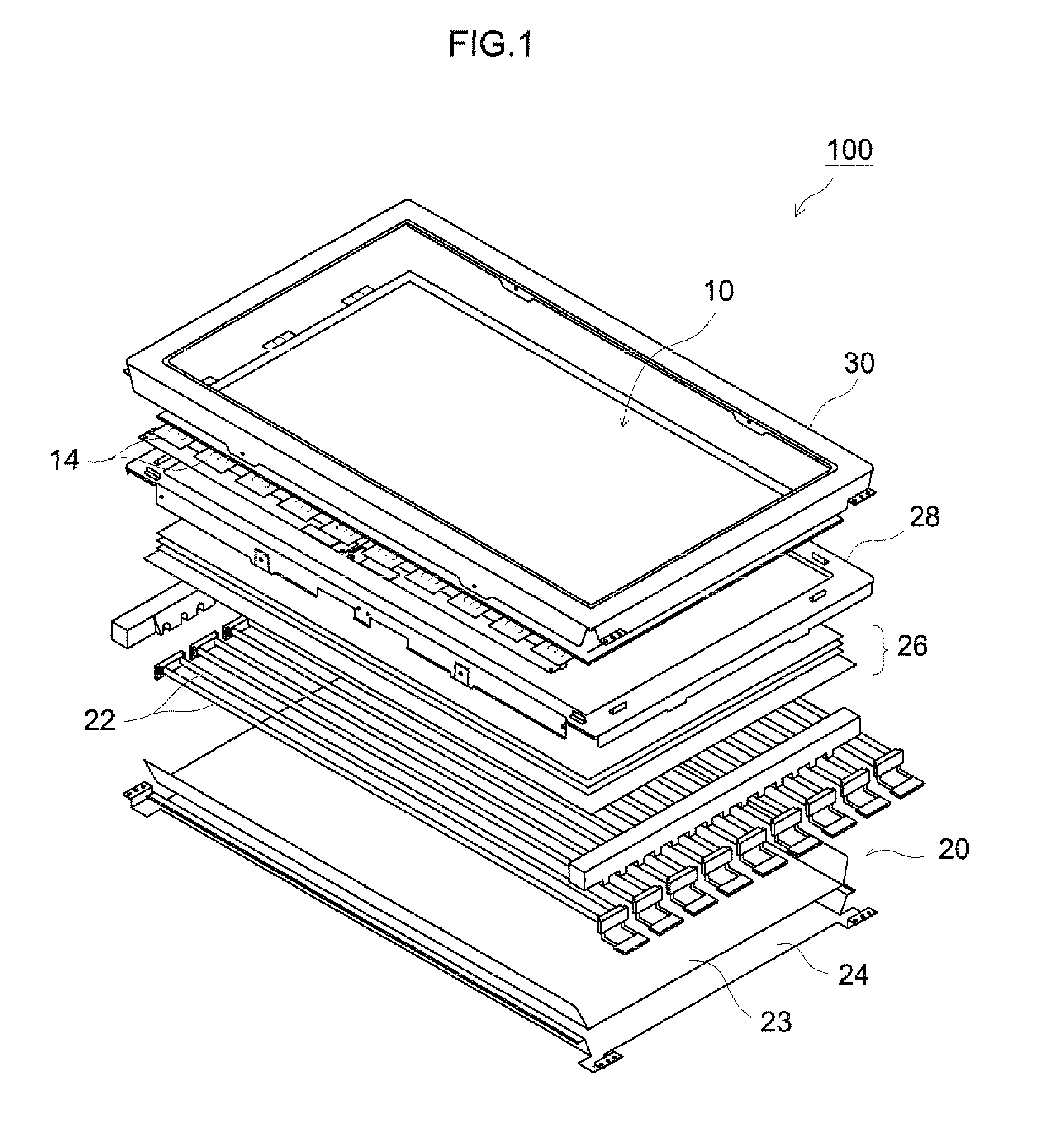
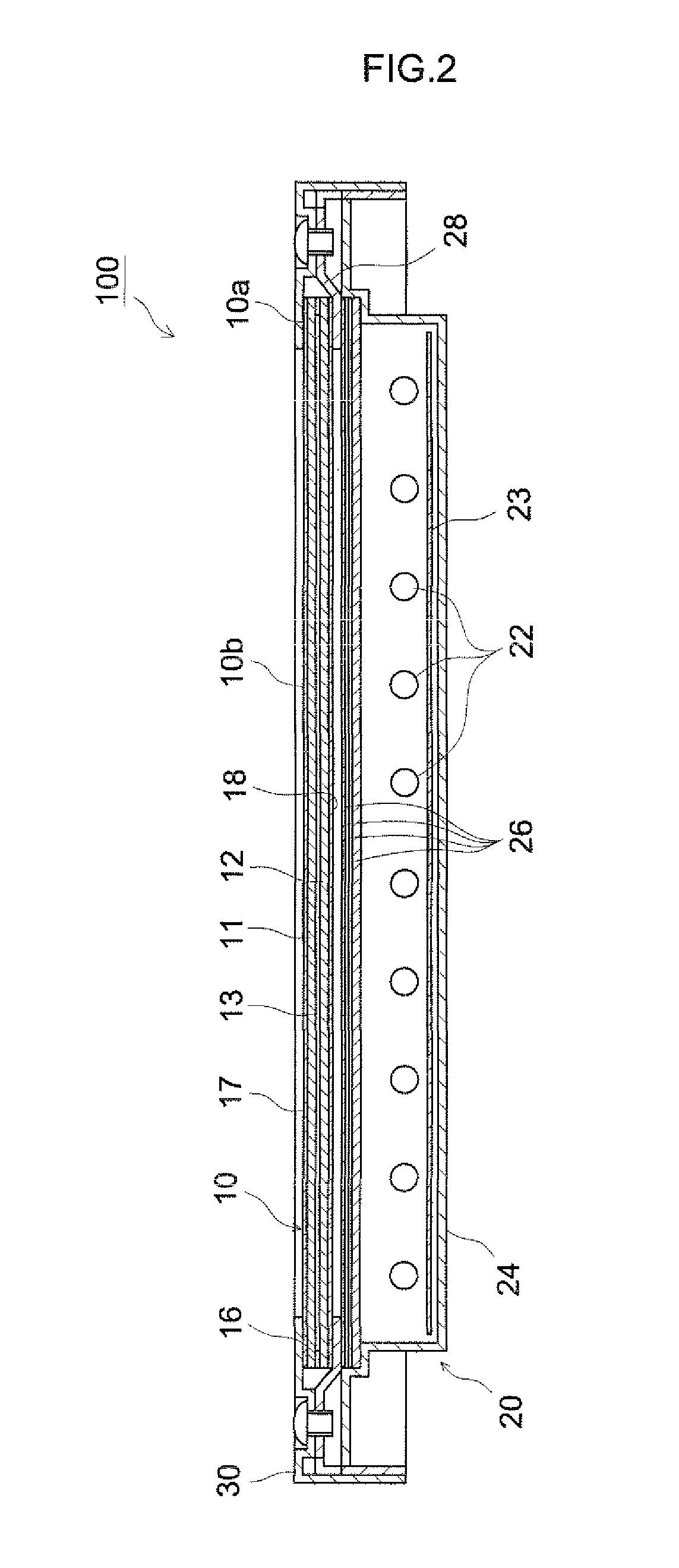
[0034]Hereinafter, with reference to FIG. 1 through FIG. 3, a liquid crystal display device 100 of an active matrix system ...


PUM

PropertyMeasurementUnit
Areaaaaaaaaaaa

Abstract

According to a liquid crystal panel 10 provided by the present invention, in the vicinity of an inner surface of a sealing portion 16 located on a peripheral portion 10a between a pair of substrates 11 and 12 in order to hold a liquid crystal layer 13 between the substrates 11 and 12, barrier portions 49 and 59 formed of a material for forming alignment films 48 and 58 are formed to be thicker than the alignment films 48 and 58.

Description

TECHNICAL FIELD[0001]The present invention relates to a liquid crystal panel and a liquid crystal display device.BACKGROUND ART[0002]Recently, liquid crystal display devices including a liquid crystal panel are in wide use as image display devices (displays) for TVs, personal computers and the like. Such a liquid crystal panel has a structure in which a liquid crystal material is confined between a pair of glass substrates (typically, an array substrate and a color filter (CF) substrate) which are bonded together with a sealant while having a prescribed gap therebetween and held as a liquid crystal layer. The sealant is located along a peripheral portion of the glass substrates so as to surround an active area (an effective display area, namely, a display screen) and thus forms a sealing portion of the liquid crystal panel in order to confine the liquid crystal material between the substrates.[0003]On the glass substrates, an alignment film of a resin material (typically, polyimide)...

Claims


Application Information

Patent Timeline
IPC IPC(8): G02F1/1337G02F1/1339
CPCG02F1/133723G02F2001/133388G02F1/1339G02F1/133388
Inventor INOUE, TOMOHIRO
Owner SHARP KK
Why Eureka
Try Eureka