
X-ray source and x-ray photographing apparatus including the source

a technology of x-ray source and x-ray photographing apparatus, which is applied in the field of radiation imaging, can solve the problems of high temperature of target electrode, deterioration of resolution, and melting of target electrodes

Inactive Publication Date: 2011-10-20
CANON KK
View PDF0 Cites 41 Cited by
  • Summary
  • Abstract
  • Description
  • Claims
  • Application Information

AI Technical Summary

Benefits of technology

[0008]The present invention is directed to an X-ray source and an X-ray photographing apparatus capable of suppressing a change in a focal size according to an irradiation direction.
[0009]According to an aspect of the present invention, an X-ray source includes an electron-beam generation unit generating an electron beam, and a transmission type target electrode to be irradiated with the electron beam to generate an X-ray, wherein a plurality of convex portions each having an inclined surface with respect to an incident direction of the electron beam is formed on a surface of the transmission type target electrode. According to the present invention, it is possible to suppress a change in a focal size of the X-ray according to an irradiation direction while radiating heat of the transmission type target electrode with high efficiency.

Problems solved by technology

If heat radiation is not effectively evacuated from the vacuum chamber, then temperature of the target electrode rises and the target electrode often melts.
However, when the technique for tilting the surface of the target electrode and that for providing very small irregularities on the surface of the target electrode are adopted, the X-ray generating apparatus effects different focal sizes according to X-ray extraction directions and the resolution tends to deteriorate.
In other words, it is a burden on the user to make complicated preparations for the X-ray photography that requires high resolution when the conventional X-ray generating apparatus is used.

Method used


Image

  • X-ray source and x-ray photographing apparatus including the source
  • X-ray source and x-ray photographing apparatus including the source
  • X-ray source and x-ray photographing apparatus including the source

Examples


Embodiment Construction

[0019]Various exemplary embodiments, features, and aspects of the invention will be described in detail below with reference to the drawings.

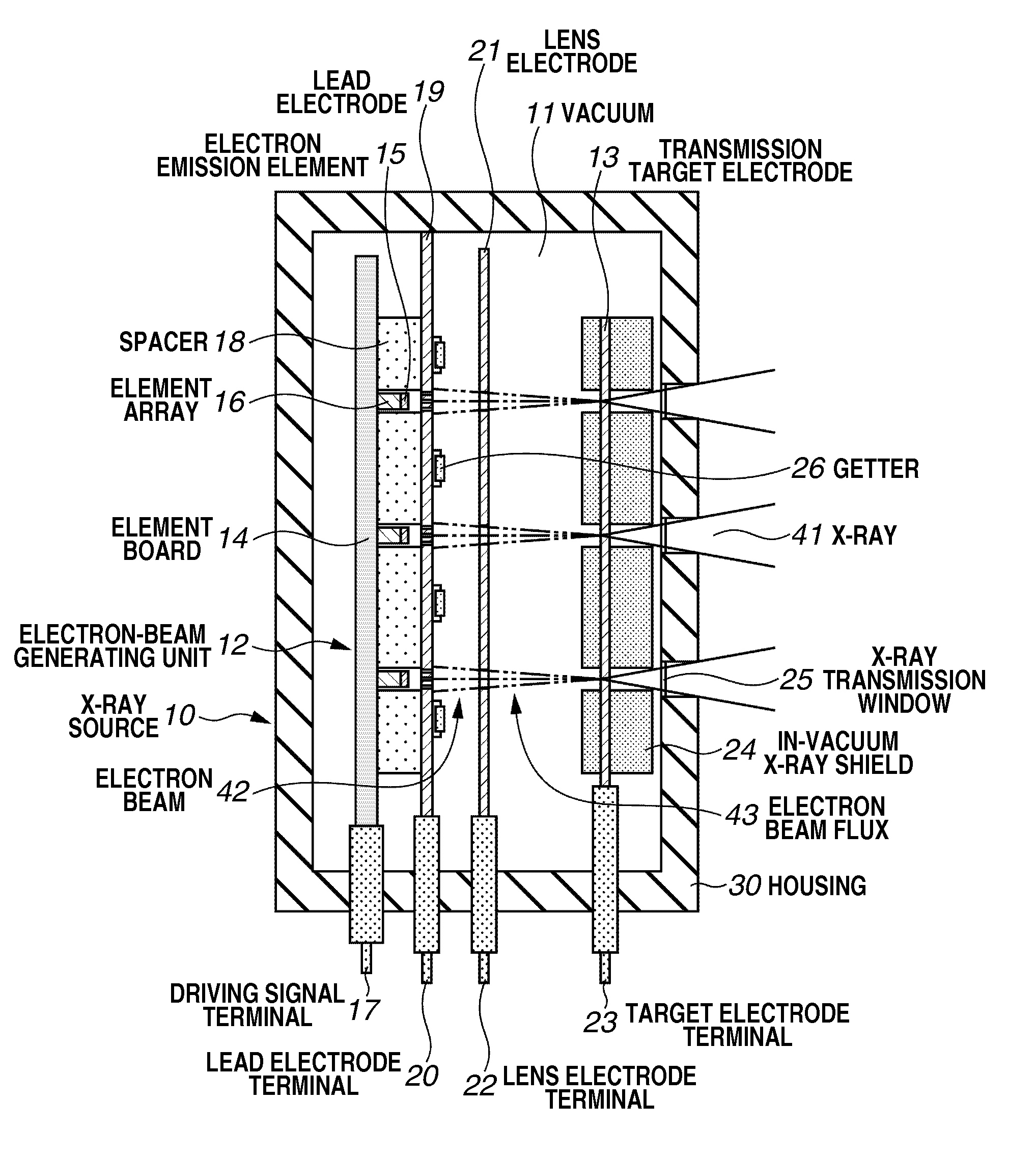
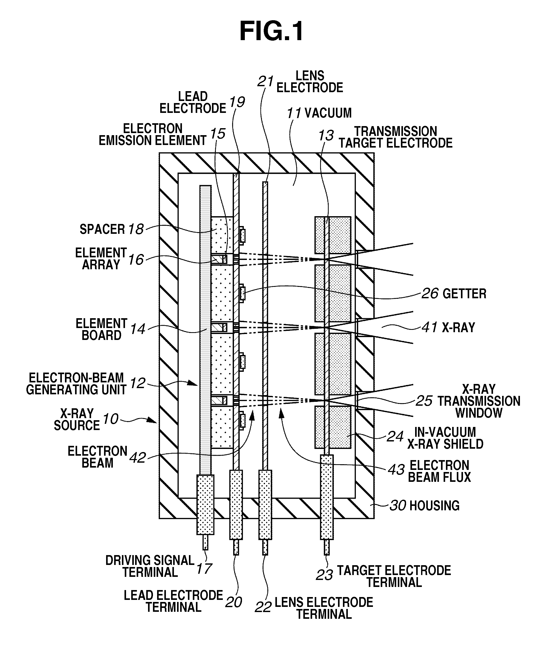
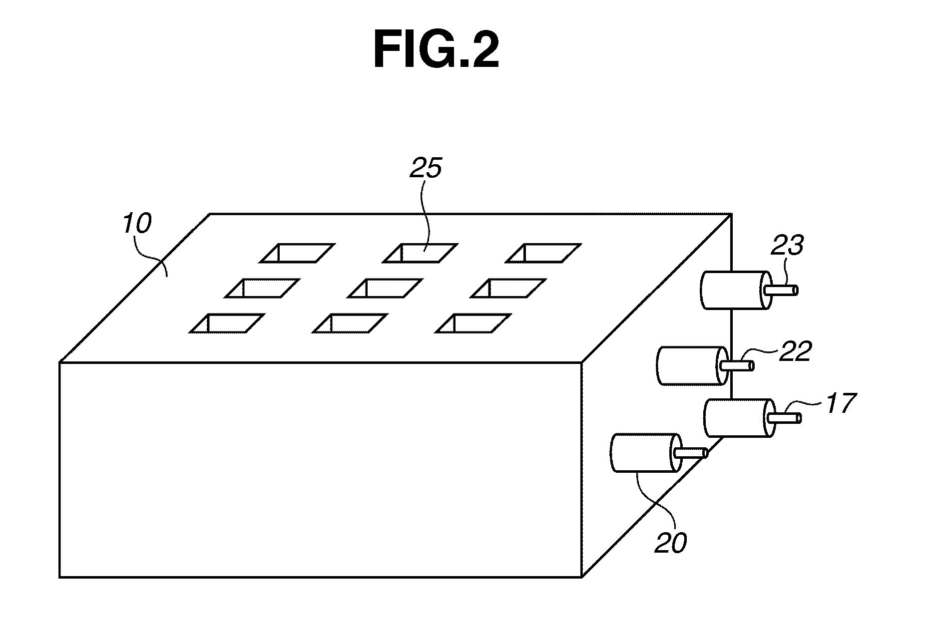
[0020]An X-ray source according to a first exemplary embodiment of the present invention will first be described. FIG. 1 illustrates an internal configuration of the X-ray source according to a first exemplary embodiment of the present invention. FIG. 2 is an external view of the X-ray source according to the first exemplary embodiment.

[0021]In an X-ray source 10 according to the first exemplary embodiment, an interior of a housing 30 is a vacuum chamber 11. An electron-beam generating unit 12 and a transmission type target electrode 13 are arranged in the vacuum chamber 11. An element board 14 and an element array 16 are provided in the electron-beam generation unit 12. The element array 16 is made of a high-melting-point metal such as molybdenum and has a diameter of, for example, 5 mm. An electron emission element 15 is mounted on a top of t...


PUM

PropertyMeasurementUnit
angleaaaaaaaaaa
heightaaaaaaaaaa
diameteraaaaaaaaaa

Abstract

An X-ray source includes an electron-beam generating unit that generates an electron beam, and a transmission type target electrode to be irradiated with the electron beam to generate X-ray radiation. A plurality of convex portions each having an inclined surface with respect to an incident direction of the electron beam is formed on a surface of the transmission type target electrode.

Description

BACKGROUND OF THE INVENTION[0001]1. Field of the Invention[0002]The present invention relates to radiation imaging, more specifically to an X-ray source and an X-ray photographing apparatus each including a transmission type target electrode.[0003]2. Description of the Related Art[0004]A thermionic source is conventionally used as an electron source of an X-ray generating apparatus. In an X-ray generating apparatus that uses a thermionic source, part of thermally emitted electrons (thermions) emitted from a filament heated to high temperature are formed into an electron flux of a predetermined shape through a Wehnelt electrode, an extraction electrode, an accelerating electrode, and a lens electrode; and the electron flux is accelerated to have high energy. A target electrode including a metal such as tungsten is irradiated with the electron flux, thereby generating X-rays. As the thermionic source, there is known a small-sized thermionic source such as an impregnated hot-cathode el...

Claims


Application Information

Patent Timeline
Patent Type & Authority Applications(United States)
IPC IPC(8): G01N23/04H01J35/00
CPCH01J35/065H01J35/08H01J35/16H01J35/18H01J35/20H01J2235/205H01J2235/068H01J2235/087H01J2235/163H01J2235/186H01J2235/062H01J35/116H01J35/186
Inventor UEDA, KAZUYUKITSUJII, OSAMUOGURA, TAKAONOMURA, ICHIRO
Owner CANON KK
Learn More