
Modular Cabinet For Ultra-Low Temperature Freezer

a modular cabinet and freezer technology, applied in the field of ultra-low temperature freezers, can solve the problems of time-consuming, messy, and inherent variation of the process

Inactive Publication Date: 2011-10-27
THERMO FISHER SCI ASHEVILLE
View PDF15 Cites 9 Cited by
  • Summary
  • Abstract
  • Description
  • Claims
  • Application Information

AI Technical Summary

Benefits of technology

[0009]In one embodiment, a storage cabinet is provided for an ultra-low temperature freezer. The cabinet includes a base platform, a plurality of side structural insulated panels, each defining a side wall of the storage cabinet, and a plurality of generally vertically oriented posts extending from the base platform. At least one of the plurality of generally vertically oriented posts has a slot for receiving an edge portion of one of the insulated panels therealong. The slot may have a generally U-shaped profile that surrounds the edge portion of one of the insulated panels. The channel may be configured to receive one of insulation, tubing, or wiring of the freezer therethrough. An outer skin may surround the insulated panels and define an outer surface of the freezer, with the volume between the outer skin and the insulated panels being effectively free of expanding, foamed-in-place insulation.
[0010]In a specific embodiment, the cabinet includes a roll-bond evaporator adjacent one of the insulated panels and configured to fluidly communicate with a refrigeration system of the freezer for cooling an interior of the storage cabinet. The roll-bond evaporator may be coupled to one or more of the generally vertically oriented posts. A volume between the roll-bond evaporator and the adjacent side insulated panel may be effectively free of expanding, foamed-in place insulation. Alternatively, or additionally, the roll-bond evaporator may include a plurality of evaporator panels, with each evaporator panel being oriented generally parallel to one of the insulated panels. In a specific embodiment, the storage cabinet includes a plurality of roll-bond evaporator panels, each adjacent one of the insulated panels, and a plurality of capillary tubes, with each of the capillary tubes being in fluid communication with one of the roll-bond evaporator panels. In this embodiment, each of the capillary tubes is configured to fluidly communicate with a refrigeration system of the freezer for cooling the interior of the storage cabinet. Respective volumes between the roll-bond evaporator panels and the respectively adjacent side insulated panels may be effectively free of expanding, foamed-in place insulation.
[0011]In another specific embodiment, the cabinet includes an evaporator coil that is secured to one of the generally vertically oriented posts, with the evaporator coil being configured to fluidly communicate with a refrigeration system of the freezer for cooling an interior of the storage cabinet. In this specific embodiment, a spacer element is disposed between the evaporator coil and the one of the generally vertically oriented posts. Respective volumes between side wall portions of the evaporator coil and the respectively adjacent side insulated panels may be effectively free of expanding, foamed-in place insulation.

Problems solved by technology

However, with the low storage temperatures involved, and the need to periodically insert and remove particular samples from the interior of the storage cabinet, various problems may arise.
This process is time consuming, messy and has inherent variation.

Method used


Image

  • Modular Cabinet For Ultra-Low Temperature Freezer
  • Modular Cabinet For Ultra-Low Temperature Freezer
  • Modular Cabinet For Ultra-Low Temperature Freezer

Examples


Embodiment Construction

[0036]The invention will now be described with reference to the figures, in which like reference numerals refer to like parts throughout.

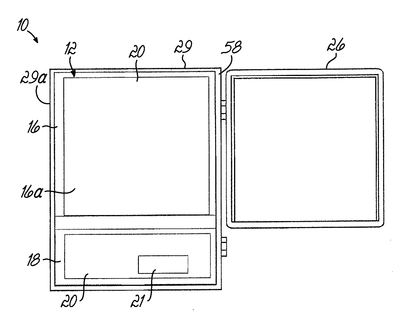
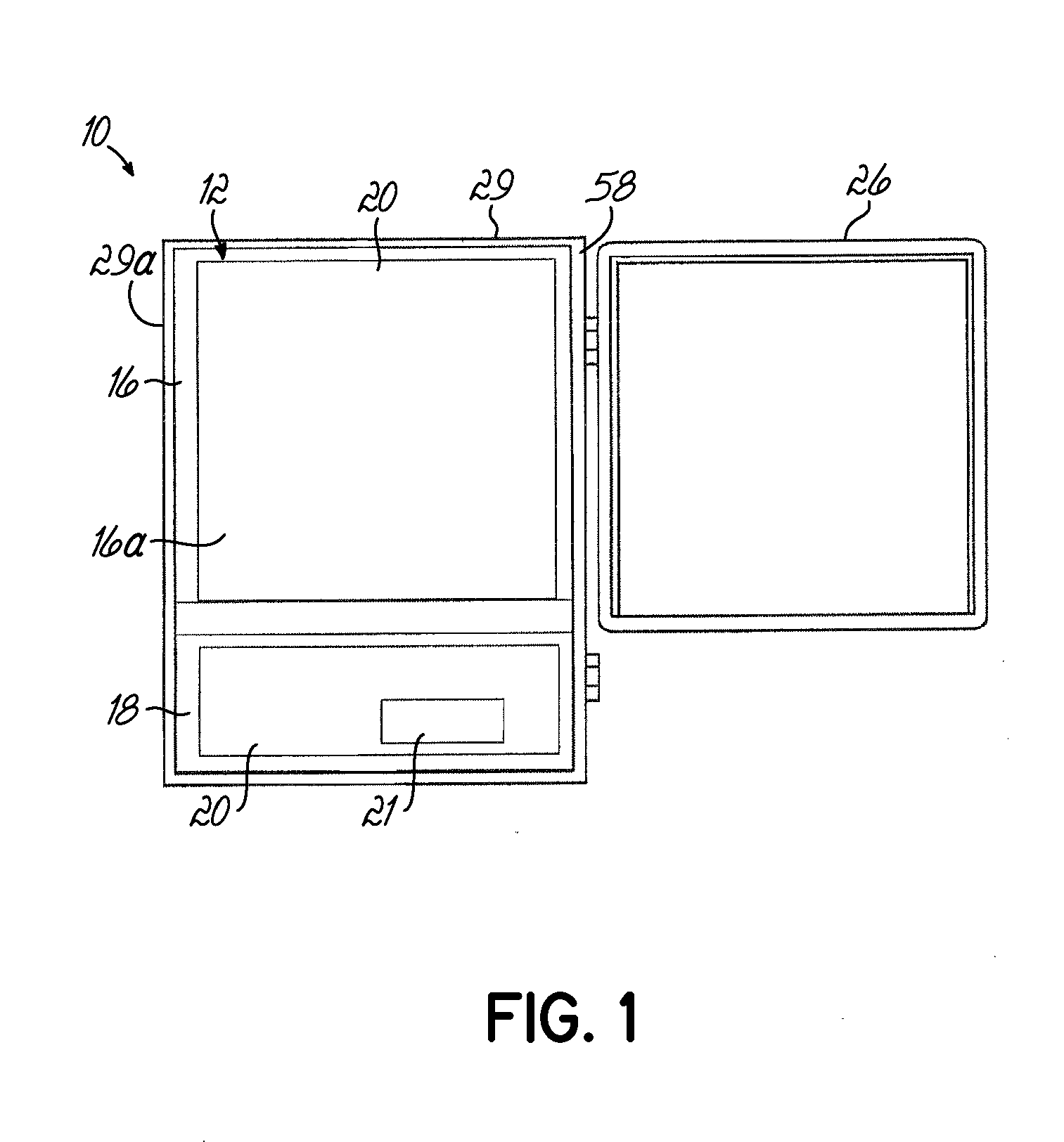
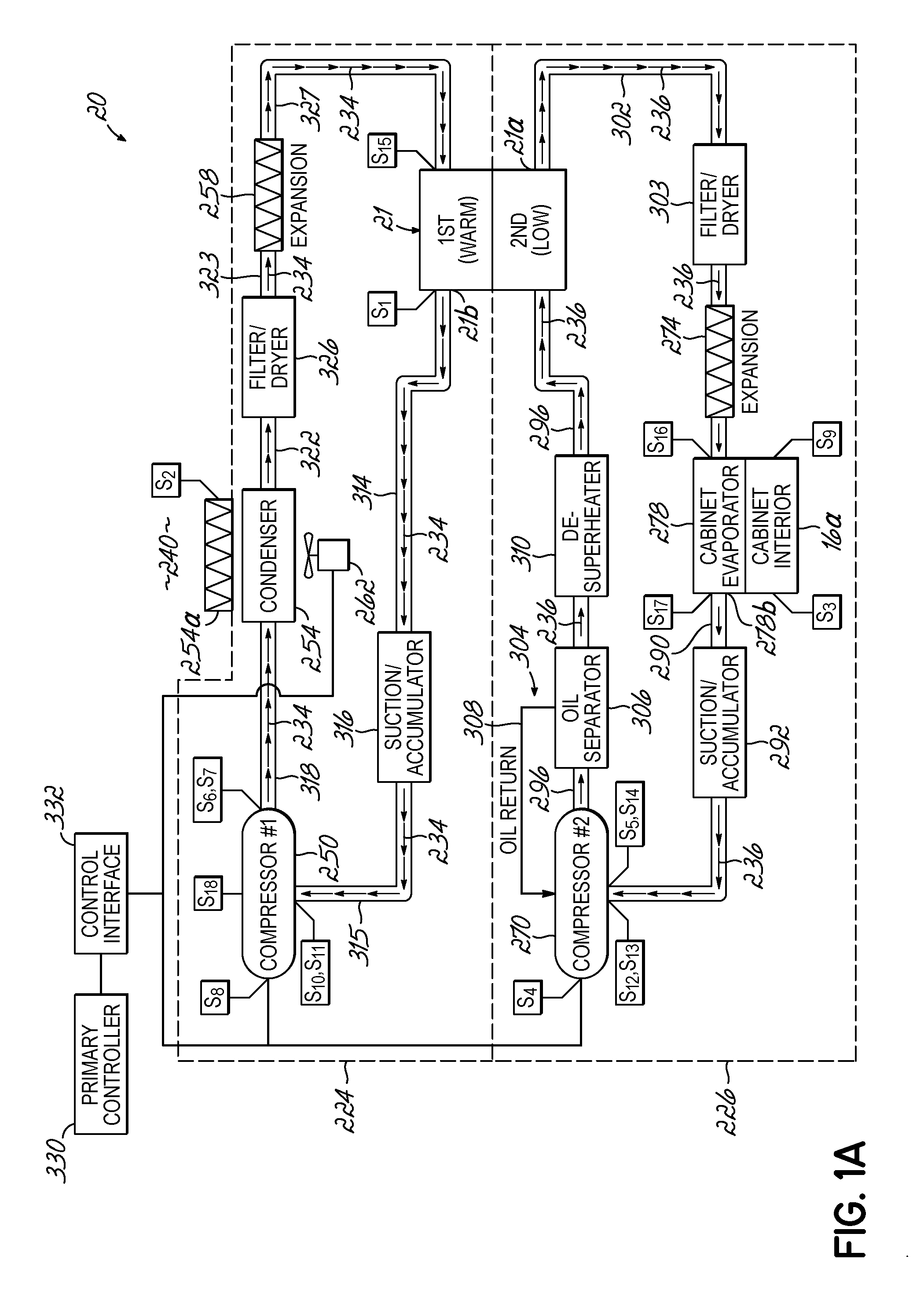
[0037]With reference to the figures and particularly to FIG. 1, an ultra-low temperature freezer (“ULT”) 10 is illustrated in accordance with one embodiment of the present invention. The ULT 10 includes a housing or framework 12 that includes a storage cabinet or compartment 16 supported above a deck 18. The deck 18, in turn, supports one or more components of a refrigeration system 20 (schematically depicted) that is configured to cool the interior 16a of cabinet 16. In this regard, the deck 18 may support one or more compressors of a single refrigerant system or one or more compressors of a two-stage cascade refrigeration system, for example. The system 20 may, for example, include a heat exchanger 21 (schematically depicted) that is supported within the deck 18 and which ultimately fluidly communicates with an evaporator of the system 20, explai...


PUM

PropertyMeasurementUnit
cryogenic temperaturesaaaaaaaaaa
temperatureaaaaaaaaaa

Abstract

A storage cabinet (16) is provided for an ultra-low temperature freezer (10). The cabinet (16) includes a base platform (62a), a plurality of side structural insulated panels (45, 50, 55) each defining a side wall of the storage cabinet (16), and a plurality of generally vertically oriented posts (40) extending from the base platform (62a). Each of the plurality of vertically oriented posts (40) has a slot (40a) for receiving an edge portion (45a, 50a, 55a) of one of the insulated panels (45, 50, 55) therealong. The slot (40a) may have a generally U-shaped profile that surrounds the edge portion (45a, 50a, 55a) of one of the insulated panels (45, 50, 55). At least one of the generally vertically oriented posts (40) has a channel (40c) that extends along a longitudinal dimension thereof, the channel (40c) being configured to receive one of insulation, tubing, or wiring of the freezer therethrough.

Description

CROSS-REFERENCE TO RELATED APPLICATION[0001]This application claims the filing benefit of U.S. Provisional Patent Application Ser. No. 61 / 101,574 filed Sep. 30, 2008, the disclosure of which is hereby expressly incorporated by reference herein in its entirety.FIELD OF THE INVENTION[0002]The present invention relates generally to ultra-low temperature freezers and, more particularly, to the construction of a modular storage cabinet for an ultra-low temperature freezer.BACKGROUND OF THE INVENTION[0003]There has been a rapid increase in demand for refrigeration systems that can attain a very low temperature range. One type of system that can reach such temperatures is known as an ultra-low temperature freezer (“ULT”), which can maintain a very low range of temperatures. The ULT can be used to store and protect a variety of objects including critical biological samples, for example, so that they are safely and securely stored at a desired temperature for extended periods of time within ...

Claims


Application Information

Patent Timeline
Patent Type & Authority Applications(United States)
IPC IPC(8): F25D3/00B23P15/26F25D23/06
CPCF25B7/00F25B39/024Y10T29/49357F25D23/065F25D23/062
Inventor SMITH, DENNIS H.SWIFT, TODDBRAMLETT, KEVIN D.NERUR, SANTOSHTIPTON, WALTER JEFFMORRIS, WENDELL
Owner THERMO FISHER SCI ASHEVILLE
Learn More