Coating method for gas delivery system

a gas delivery system and coating technology, applied in the direction of plasma technique, mechanical equipment, transportation and packaging, etc., can solve the problems of damage to the inner surface of the gas passage, high corrosion of halogen-containing process gases,

Active Publication Date: 2011-10-27
LAM RES CORP
View PDF3 Cites 213 Cited by
  • Summary
  • Abstract
  • Description
  • Claims
  • Application Information

AI Technical Summary

Problems solved by technology

Halogen-containing process gases are highly corrosiv

Method used


Image

  • Coating method for gas delivery system
  • Coating method for gas delivery system
  • Coating method for gas delivery system

Examples


Embodiment Construction

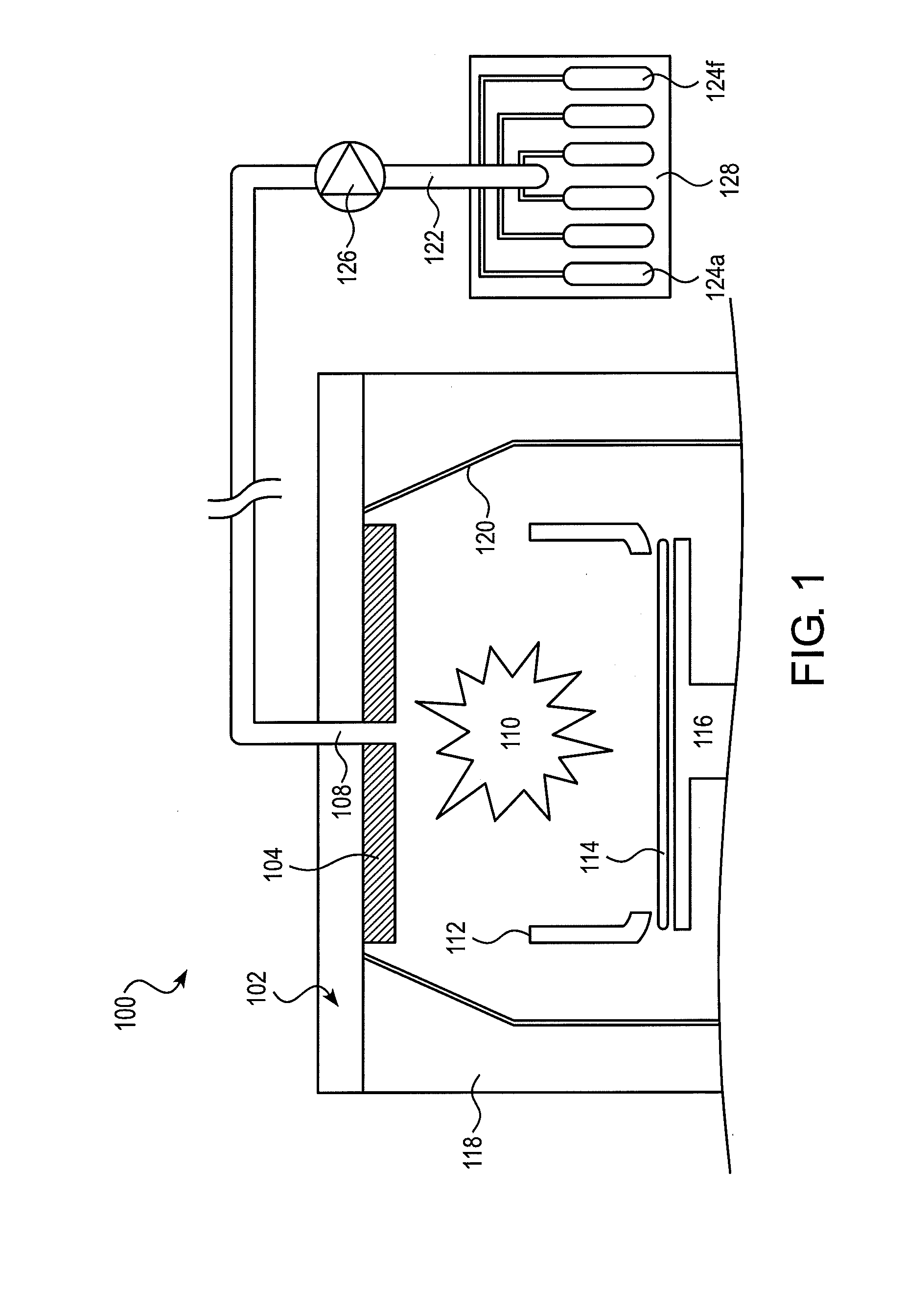
[0006]FIG. 1 shows a simplified cross-sectional view of a plasma processing system 100. Generally, one or more process gases are flowed into chamber 102 through an inlet 108 from gas delivery system 122. These process gases may be subsequently ionized to form a plasma 110, in order to process (e.g. etching or depositing on) exposed areas of substrate 114, such as a semiconductor substrate or a glass panel, positioned on an electrostatic chuck 116. Showerhead electrode 120, along with liner 112, help to optimally focus plasma 110 onto substrate 114.

[0007]Gas delivery system 122 can include one or more mass flow controllers connected to compressed gas cylinders 124a-f containing plasma processing gases (e.g., C4F3, C4F6, CHF3, CH2F3, CF4, HBr, CH3F, C2F4, N2, O2, Ar, Xe, He, H2, NH3, SF6, BCl3, Cl2, WF6, etc.). Gas cylinders 124a-f may be further protected by an enclosure 128 that provides local exhaust ventilation. Mass flow controller 126 can be a self-contained device (consisting o...


PUM

PropertyMeasurementUnit
Temperatureaaaaaaaaaa
Timeaaaaaaaaaa

Abstract

A method of coating the inner surfaces of gas passages of a gas delivery system for a plasma process system such as a plasma etching system includes (a) flowing a fluidic precursor of a corrosion-resistant material through the gas passages and depositing a layer of the fluidic precursor to completely coat the inner surfaces of the gas passages; (b) removing excess fluidic precursor from the inner surfaces; (c) curing the deposited layer of the fluidic precursor to form a corrosion-resistant material coating.

Description

BACKGROUND OF THE DISCLOSURE[0001]In the processing of a substrate, e.g., a semiconductor substrate or a glass panel such as one used in flat panel display manufacturing, plasma is often employed. As part of the processing of a substrate (plasma etching, chemical vapor deposition, plasma enhanced chemical vapor deposition, physical vapor deposition, etc.) for example, the substrate is divided into a plurality of dies, or rectangular areas, each of which will become an integrated circuit. The substrate is then processed in a series of steps in which materials are selectively removed (etching) and added (deposition) in order to form electrical components thereon.[0002]In an exemplary plasma process, a substrate is coated with a thin film of hardened emulsion (i.e., such as a photoresist mask) prior to etching. Areas of the hardened emulsion are then selectively removed, causing parts of the underlying substrate to become exposed. The substrate is then placed in a chamber of a plasma p...

Claims


Application Information

Patent Timeline
IPC IPC(8): C23F1/08B05D7/22
CPCB05D7/222B05D1/30F17D1/04H01L21/67069H01J37/3244H01J37/32495H01J2237/3341F17D5/005Y10T137/8593C23C16/50H05H1/46C23C16/0245H01L21/20H01L21/0262
Inventor KENWORTHY, IANOUTKA, DUANEHAO, FANGLISHARPLESS, LEONARDDU, YIJUN
Owner LAM RES CORP
Why Eureka
Try Eureka