Wear and friction control of metal rope and sheave interfaces

a technology of friction control and metal rope, applied in the field of elevator systems, can solve the problems of traction force between the rope and the sheave, wear and friction of the sheave and the wire rope, and limitations on their us

Inactive Publication Date: 2011-10-27
OTIS ELEVATOR CO
View PDF11 Cites 13 Cited by
  • Summary
  • Abstract
  • Description
  • Claims
  • Application Information

AI Technical Summary

Benefits of technology

[0008]The invention relates to a sheave device and method for making it. The sheave device is designed for use in an elevator system having at least one sheave in combination with a rope or other moving friction element of the elevator system. The present invention places a coating on the sheave body on at least the portion of the sheave body that is to engage the friction element. The coating provides a wear coefficient on the sheave body of less than 2.0×10⁻¹⁰ mm2n and more preferred are wear coefficients of less than 1.0×10⁻¹⁰ mm2n. This results in a reduction in wear coefficient of about 20% to 10% of the wear coefficient of the sheave without a coating (i.e., over 80% to 90% reduction). The coating and sheave body together may need to be sized to maintain the predetermined shape and size of the sheave prior to coating.

Problems solved by technology

The contact plus relative motion results in wear of the sheave and wire rope.
Although conventional round steel ropes and cast iron sheaves have proven very reliable and cost effective, there are limitations on their use.
One such limitation is the traction forces between the ropes and the sheave.
Both techniques reduce the durability of the ropes, however, as a result of the increased wear (wrap angle) or the increased rope pressure (undercutting).
Consequently, the greater the torque, the more friction becomes a limiting factor in the operation of the elevator.
While ropes and other friction elements in elevator systems can be modified, by a variety of methods including material selection, methods of braiding or otherwise forming a rope, and coating the rope with a friction resistant material, there has not been improvement in the friction resistance and wear experienced by sheaves.

Method used


Image

  • Wear and friction control of metal rope and sheave interfaces
  • Wear and friction control of metal rope and sheave interfaces
  • Wear and friction control of metal rope and sheave interfaces

Examples


Embodiment Construction

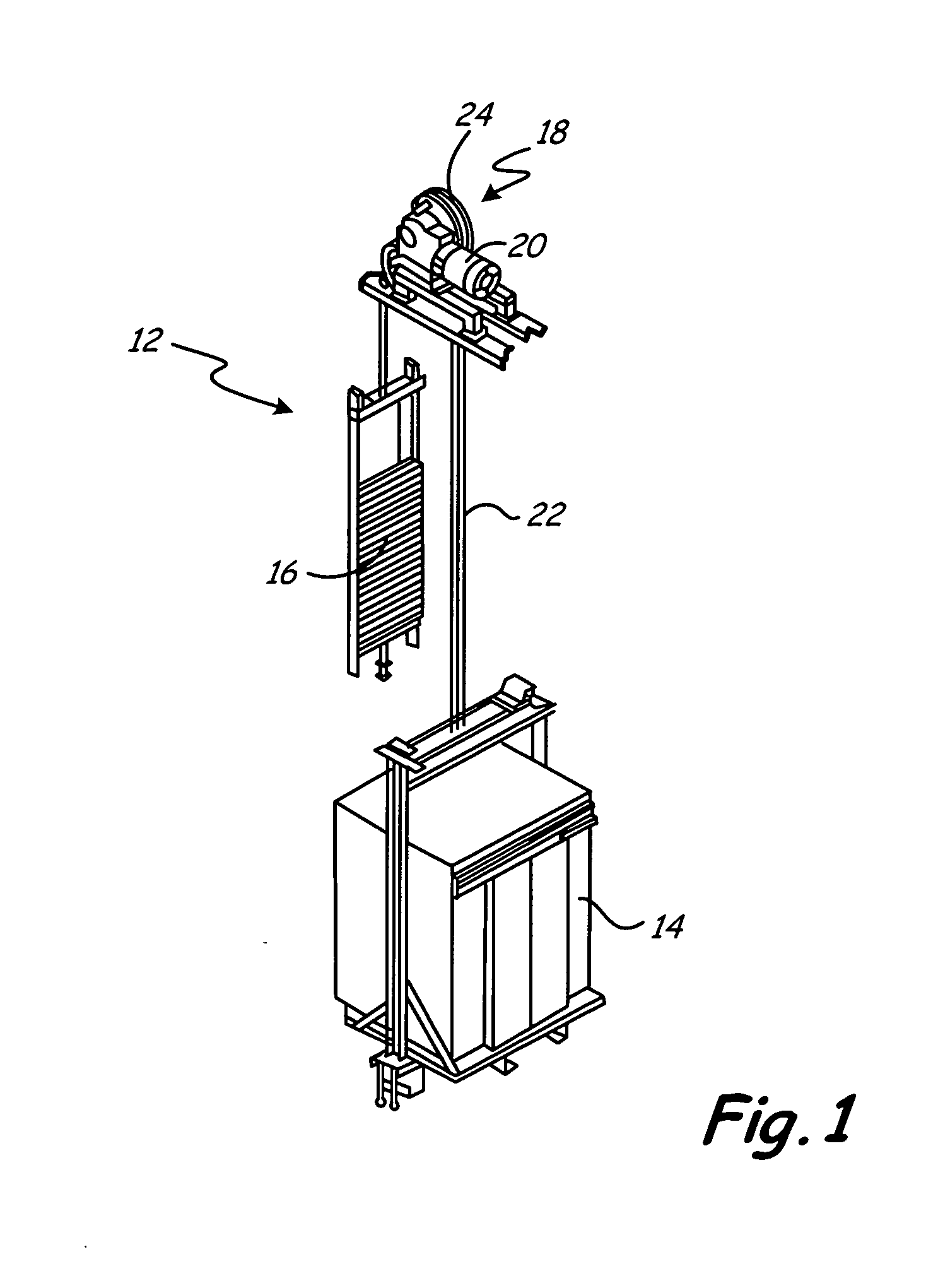
[0013]As shown in FIG. 1, a traction elevator system 12 includes a car 14, a counterweight 16, a fraction drive 18, and a machine or motor drive unit 20. The traction drive 18 includes a tension member 22, interconnecting the car 14 and the counterweight 16, and a traction sheave 24. Typically most sheaves are fabricated from cast iron, and currently Grade 40 cast iron is in use, which means that it has a strength of 40 KSI. This system as shown is a 1:1 rope system. The invention does not depend on the specific rope system but functions to repair sheave surfaces in any rope system, such as 2:1 rope systems and any other elevator system where sheaves and ropes or other tension members are employed.

[0014]To achieve the desired arrangement of the ropes in the hoistway, the elevator system could include one or more deflector sheaves. The ropes engage the deflector sheave, but unlike the traction sheave do not drive the ropes. FIG. 3 illustrates deflector sheave 37 that functions to div...


PUM


Abstract

A coated sheave (24) for use in an elevator system in having at least one rope (22) and sheave combination, where the sheave has a predetermined shape and size for engagement with at least one rope in the elevator system. A coating (27) on the sheave has a wear coefficient of at least 80% less than the wear coefficient of the sheave without the coating.

Description

BACKGROUND[0001]The present invention relates to elevator systems and more particularly to sheaves for such elevator systems.[0002]A conventional traction elevator system typically includes a car, a counterweight, two or more tension members (such as round ropes) interconnecting the car and counterweight, a traction sheave to move the ropes, and a machine to rotate the traction sheave. The machine may be either a geared or gearless machine. A geared machine permits the use of a higher speed motor, which is more compact and less costly, but requires additional maintenance and space.[0003]The ropes (whether the ropes for the car and counterweight or for the overspeed governor) can be formed from laid or twisted steel wire and the sheave (whether the drive sheave, deflector sheave or governor sheave) can be formed from cast iron. Differential tension on each side of the sheave, or rope deformation due to the tension applied, or misalignment of the sheave, can all cause relative motion ...

Claims


Application Information

Patent Timeline
Patent Type & Authority Applications(United States)
IPC IPC(8): B66B15/04
CPCB66B15/04F16H57/041F16H55/50B66B11/08
Inventor NARDI, AARON T.BEALS, JAMES T.SCHMIDT, WAYDE R.WELSH, GREGORY S.THOMPSON, MARK STEVEN
Owner OTIS ELEVATOR CO
Why Eureka
Try Eureka