
Plasma Torch Electrode with Improved Cooling Capability

a technology of electrodes and plasma arc torch, which is applied in plasma technique, welding apparatus, manufacturing tools, etc., can solve the problems of short electrode life, short electrode life, and certain components of plasma arc torch, and achieve the effect of improving local cooling and superior cooling capabilities

Inactive Publication Date: 2011-10-27
HYPERTHERM INC
View PDF2 Cites 20 Cited by
  • Summary
  • Abstract
  • Description
  • Claims
  • Application Information

AI Technical Summary

Benefits of technology

[0008]What is needed is an electrode that has superior cooling capabilities over existing electrodes and can improve the local cooling at the tip of the electrode significantly without changing the existing coolant flow within the torch. In addition, the improved electrode should be configured to align with the cooling tube so as to maintain the integrity of the electrode and the quality of the cut over many starts of the torch.
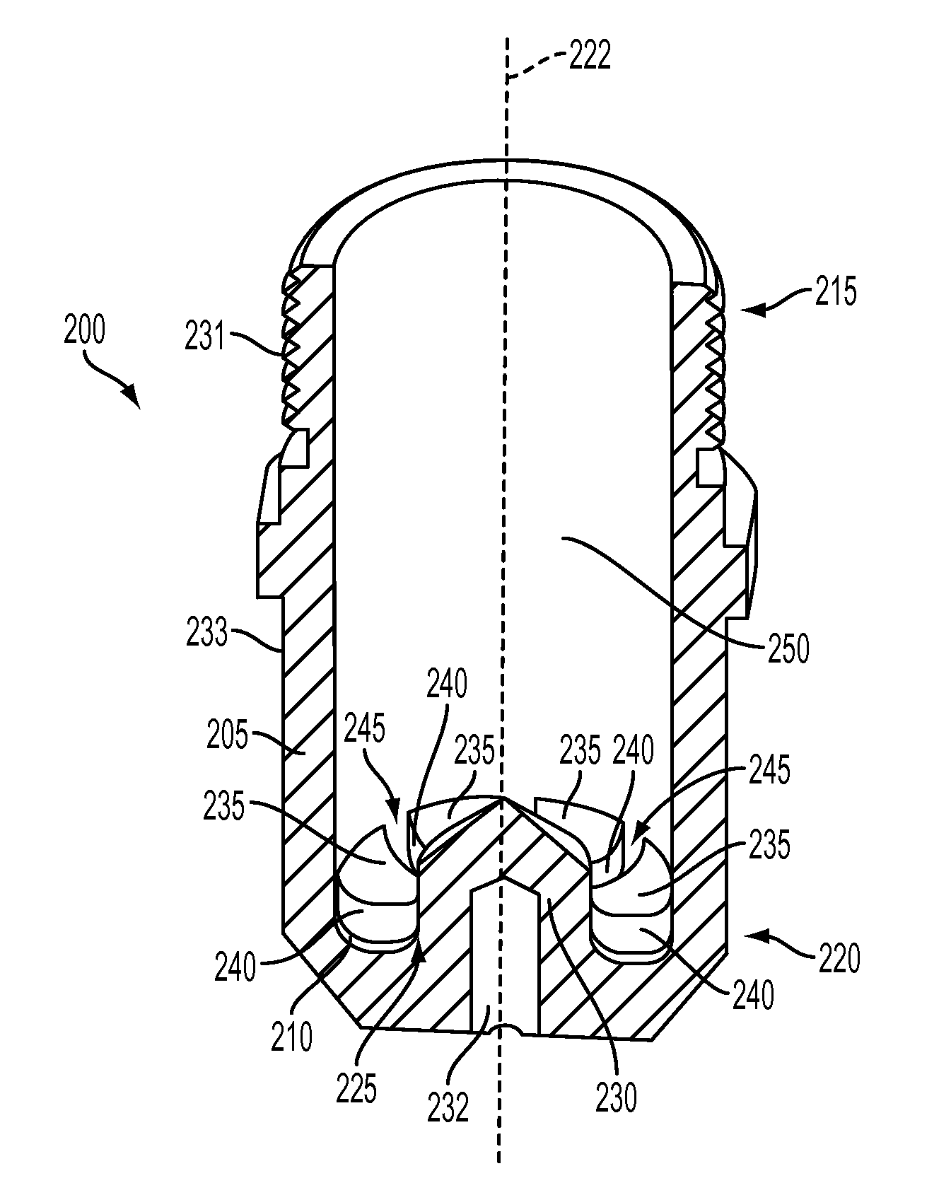
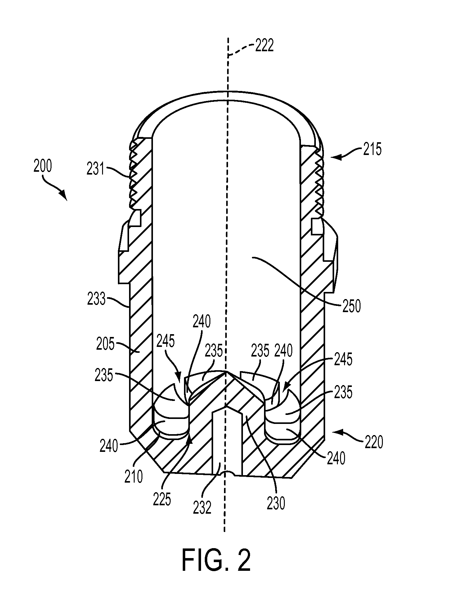
[0020]The elongated groove can provide a thermally conductive path that transfers sufficient heat from the elongated body to a cooling fluid during an operation of the plasma arc torch to prevent premature failure of the electrode.

Problems solved by technology

Certain components of a plasma arc torch deteriorate over time from use.
Short electrode life due to high erosion rate (e.g., when the plasma arc torch is operated at greater than about 350 Amps) is a common problem for many mechanized plasma arc cutting systems.
This short electrode life is mainly caused by the limitations of cooling at the electrode as well as material properties of the electrode.
For example, electrode wear typically results in reduced quality cuts.
Repeated use of a torch having a coolant tube misaligned with the electrode causes the insert material (e.g., hafnium) to rapidly wear away resulting in reduced quality cuts.

Method used


Image

  • Plasma Torch Electrode with Improved Cooling Capability
  • Plasma Torch Electrode with Improved Cooling Capability
  • Plasma Torch Electrode with Improved Cooling Capability

Examples


Embodiment Construction

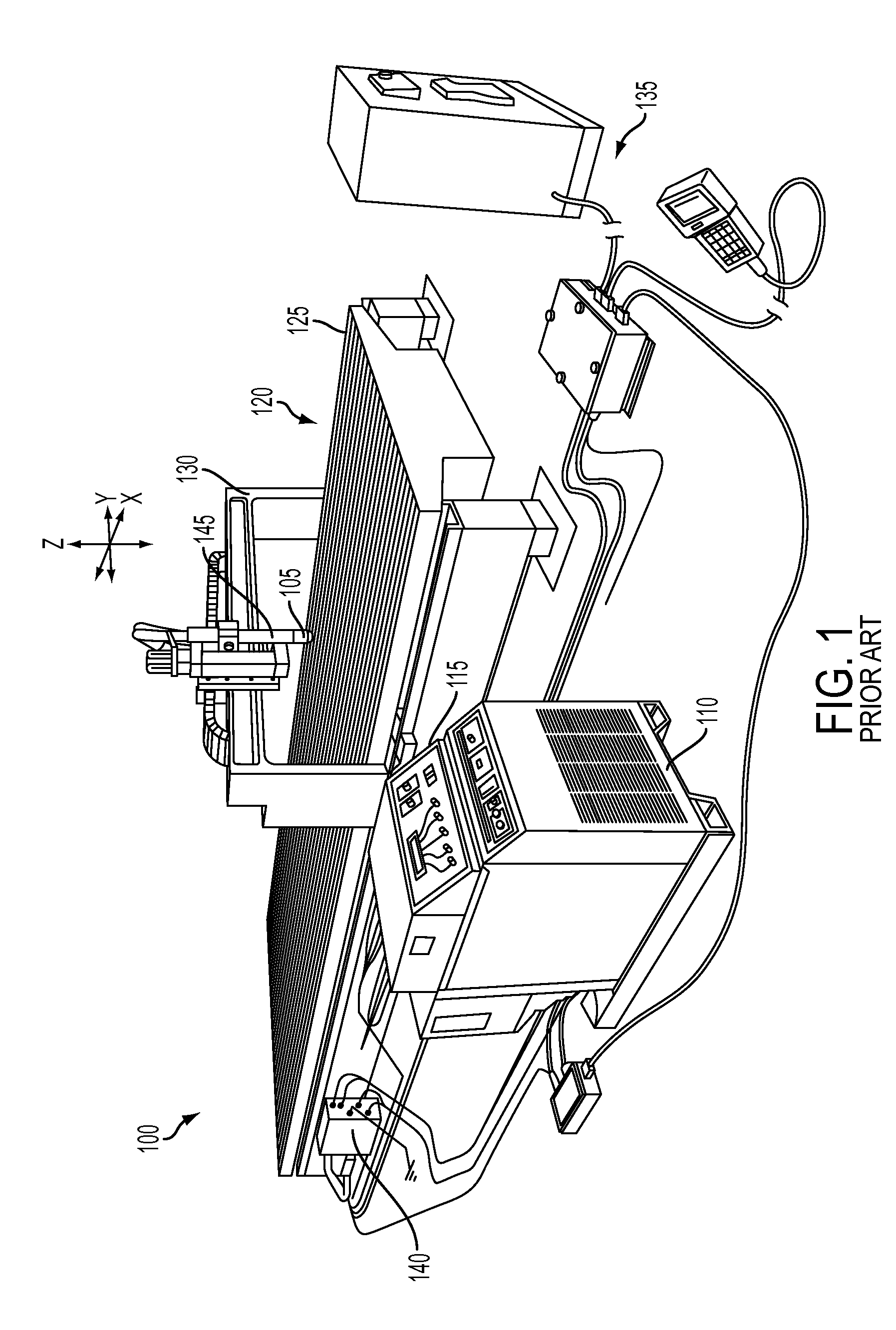
[0036]FIG. 1 shows a prior art mechanized plasma arc system 100. The system 100 includes a plasma arc torch 105 with an associated power supply 110 and a gas console 115 for generating a plasma arc. A positioning apparatus 120 includes a generally planar table 125 for fixturing of a workpiece (not shown), an overlaying gantry 130 having three motorized, mutually orthogonal linear axes X, Y, and Z with the torch 105 mounted on the Z axis, and a suitable controller 135 with three axis drives. The system also includes a high frequency, high voltage console 140 for generating a pilot arc in the torch 105. A connector system can be used to removably couple the torch 105 to a receptacle 145. The torch 105 contains consumable components, e.g., an electrode, nozzle, shield, and / or swirl ring. Proper cooling of these consumables, and in particular of the electrode, is required to maintain the quality of the cut and to prevent premature failure of the consumables.

[0037]FIG. 2 shows a cross-se...


PUM

PropertyMeasurementUnit
Electrical conductoraaaaaaaaaa

Abstract

An electrode for a plasma arc torch includes a hollow elongated body having an open end and a closed end and an end face located at the closed end inside of the hollow elongated body. The end face has a center portion. A plurality of heat exchanging elements are in thermal communication with the end face. The heat exchanging elements have side walls defining an elongated channel between adjacent heat exchanging elements. The elongated channel extends radially from the center portion to an inner surface of the elongated body. The elongated channel provides a thermally conductive path that transfers sufficient heat from the elongated body to a cooling fluid during an operation of the plasma arc torch to prevent premature failure of the electrode.

Description

RELATED APPLICATIONS[0001]This application claims the benefit of and priority to U.S. Provisional Application No. 61 / 342,932, filed Apr. 21, 2010, the entirety of which is hereby incorporated herein by reference.TECHNICAL FIELD[0002]The present invention relates generally to plasma arc cutting torches, and more particularly, to a plasma torch electrode designed to provide an improved cooling capability.BACKGROUND[0003]Plasma arc torches are widely used for cutting metallic materials and can be employed in mechanized systems for automatically processing a workpiece. The system can include the plasma arc torch, an associated power supply, a positioning apparatus and an associated controller. At least one of the plasma arc torch and the workpiece can be mounted on the positioning apparatus which provides relative motion between the torch and the workpiece to direct the plasma arc along a processing path.[0004]A plasma torch generally includes an electrode, and a nozzle having a central...

Claims


Application Information

Patent Timeline
IPC IPC(8): B23K9/00
CPCH05H1/28H05H2001/3442H05H2001/3436H05H1/34H05H1/3436H05H1/3442
Inventor YANG, YONG
Owner HYPERTHERM INC
Learn More