
Dual time alignment architecture for transmitters using EER/et amplifiers and others

a transmitter and amplifier technology, applied in the direction of rf amplifier, negative-feedback circuit arrangement, amplifier modification to reduce non-linear distortion, etc., can solve the problems of high accuracy useful time alignment, inability to work with all tdes, and limitations of techniques based on oversampling signals in the prior arts

Inactive Publication Date: 2011-10-27
SAMSUNG ELECTRONICS CO LTD
View PDF5 Cites 29 Cited by
  • Summary
  • Abstract
  • Description
  • Claims
  • Application Information

AI Technical Summary

Problems solved by technology

Other techniques are based on some type of time delay estimator (TDE) in a closed loop fashion, however not all TDEs will work and produce a high accuracy useful time alignment.
The techniques based on oversampling the signals in the prior arts have limitations.
Ten to twenty times oversampling is common and this requires a large amount of computation to perform the oversampling and the cross-correlation operations, and a large amount of information on the feedback signal is needed to achieve high accuracy in time alignment; therefore, a costly powerful DSP processor is needed.
This becomes impractical from the point of view of implementation, cost, and speed of time aligning.
Also, it is very difficult to implement the scheme of oversampling the signal followed by a cross correlation operation in a Field-Programmable Gate Array (FPGA) due to the limitation of the FPGA clock speed; therefore, these techniques do not support real-time tracking of the time delay in order to make the proper delay adjustment.
However, the techniques of computing the correlation algorithm in the prior arts have limitations.
That is, not all TDE blocks are useful in a DPD system.
Some of the designs do not have the proper computational accuracy because they try to compute the correlation between two signals by representing the signals using one bit instead of representing the digital signals with multibit.
In addition, TDEs that have been used previously do not support the dual time alignment needed for envelope elimination and restoration and envelope tracking (EER / ET) systems.

Method used


Image

  • Dual time alignment architecture for transmitters using EER/et amplifiers and others
  • Dual time alignment architecture for transmitters using EER/et amplifiers and others
  • Dual time alignment architecture for transmitters using EER/et amplifiers and others

Examples


Embodiment Construction

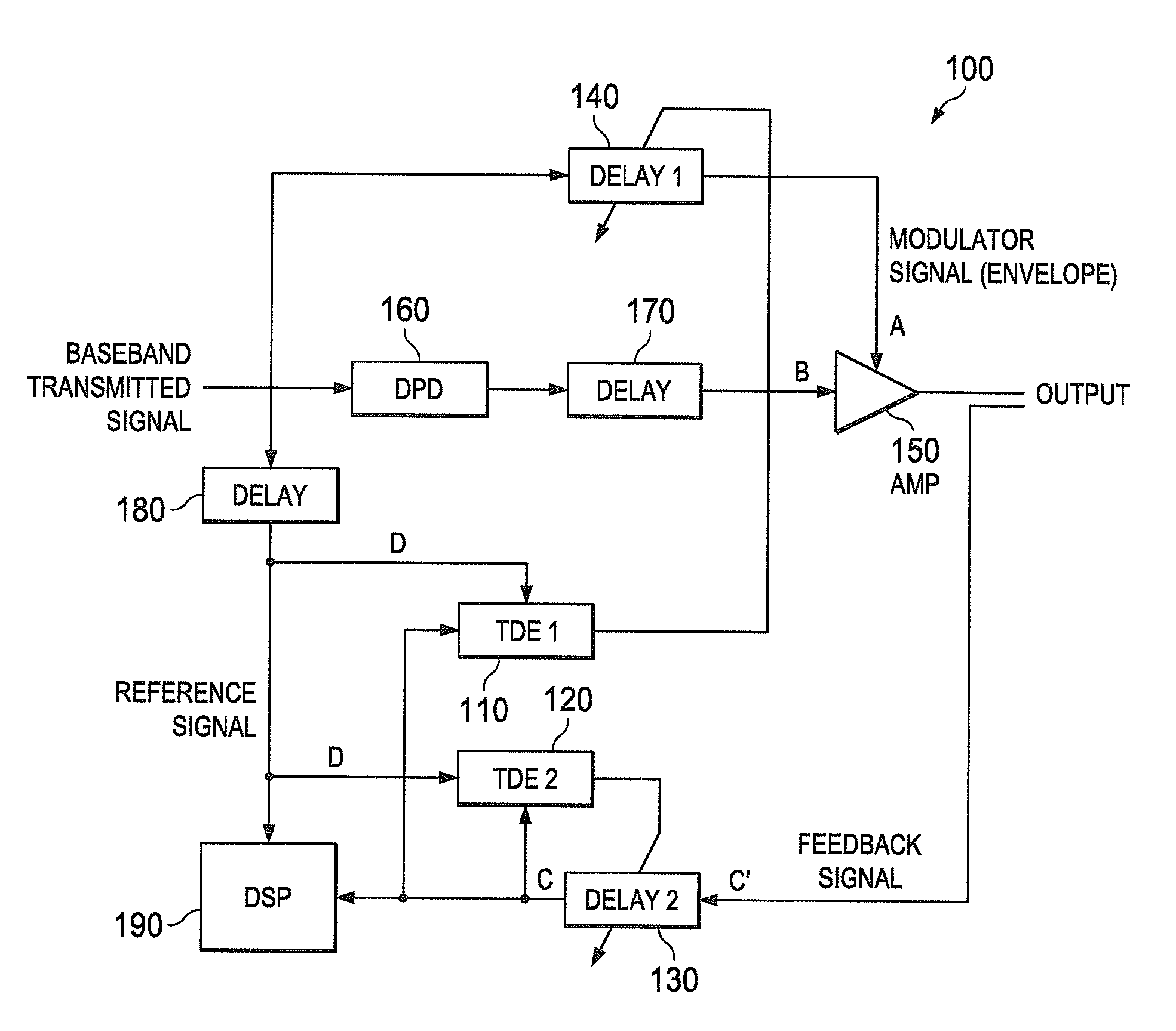
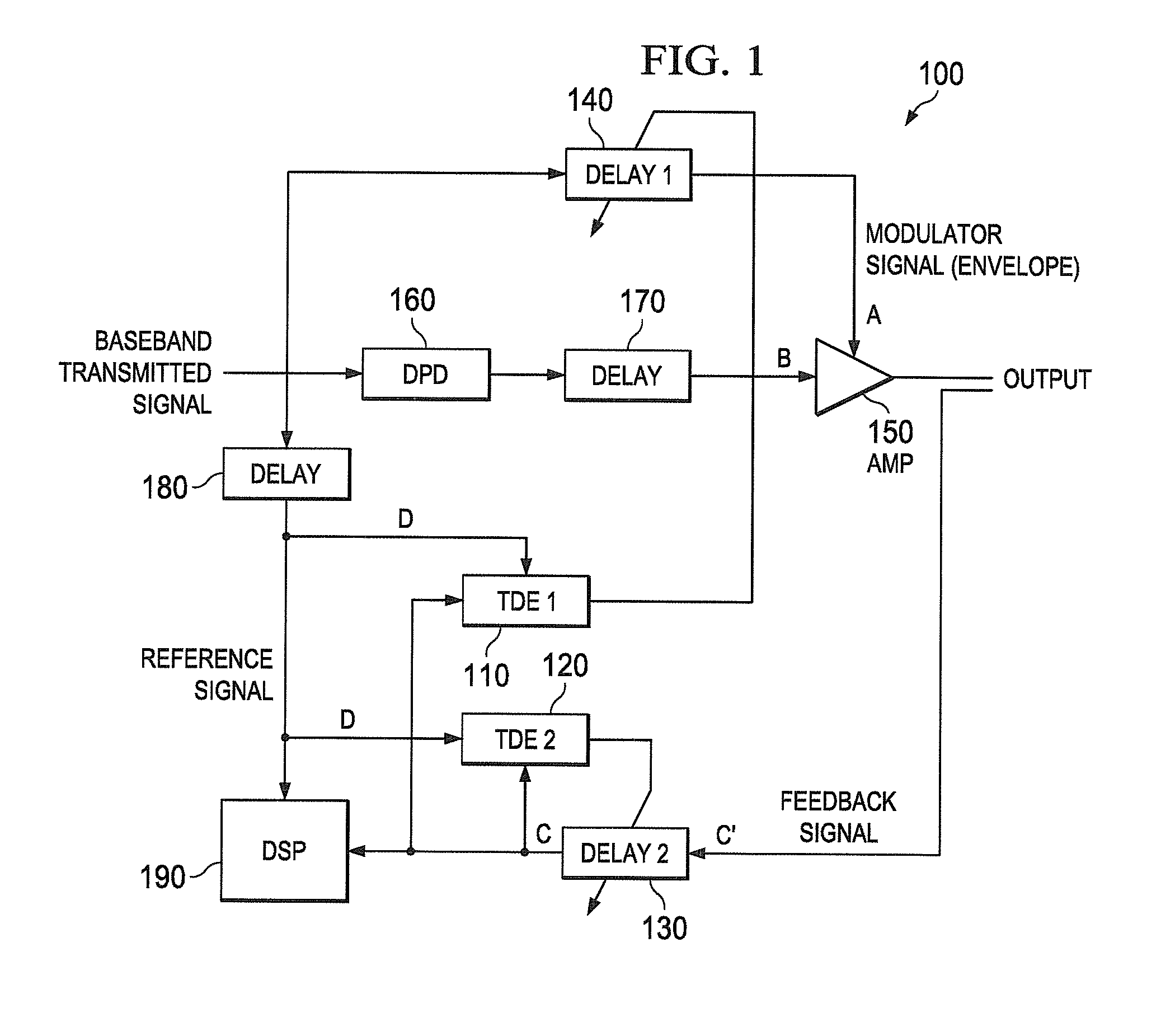
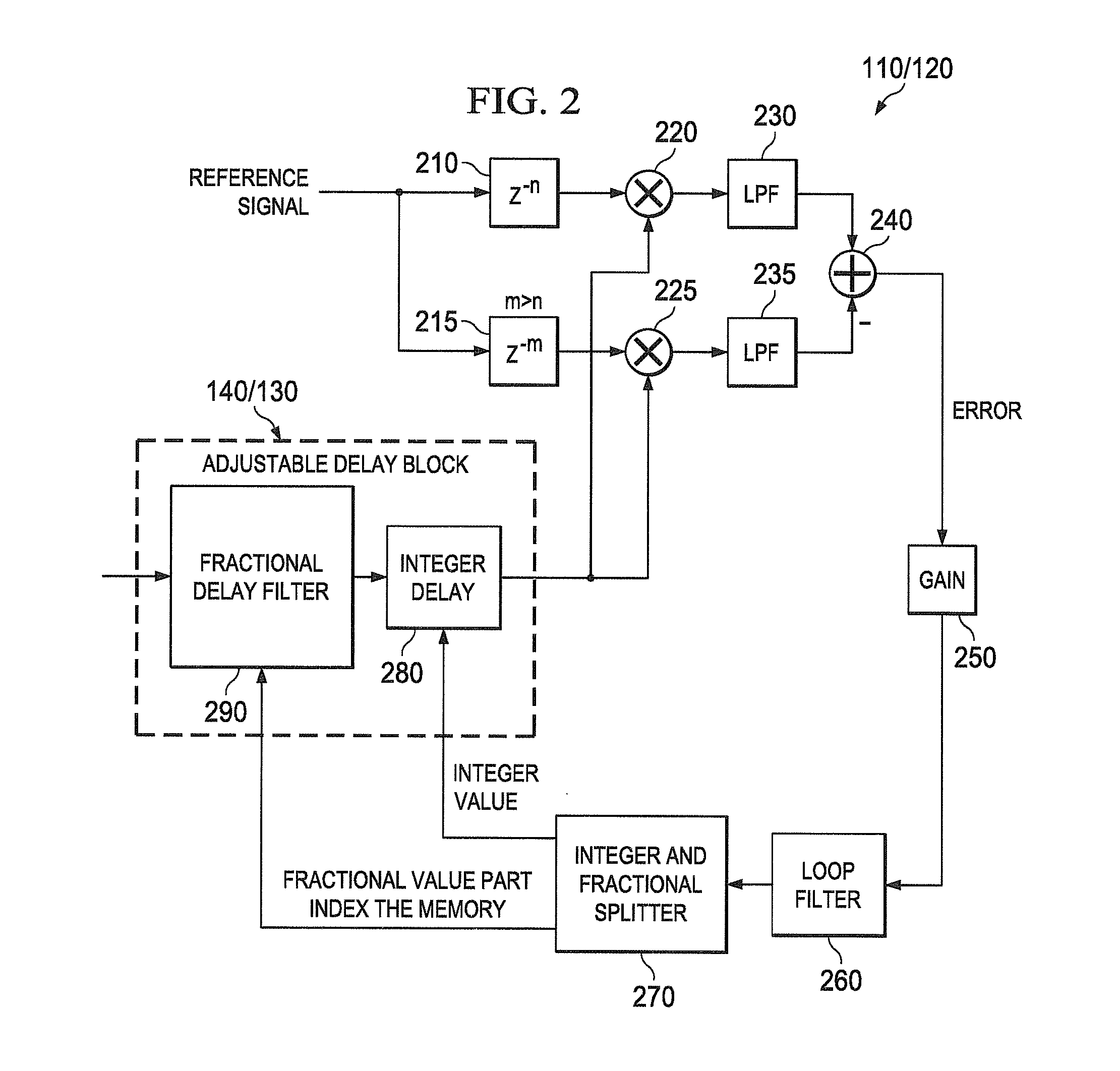
[0022]FIGS. 1 through 3, discussed below, and the various embodiments used to describe the principles of the present disclosure in this patent document are by way of illustration only and should not be construed in any way to limit the scope of the disclosure. Those skilled in the art will understand that the principles of the present disclosure may be implemented in any suitably arranged transmitter.

[0023]Radio frequency transmitters typically include a power amplifier (PA). The power amplifier may be operated in its non-linear region near saturation in order to increase the power efficiency. Due to the non-linearity of the PA, the adjacent channel leakage ratio (ACLR) level becomes unacceptable since the output spectrum will expand and cause interference with adjacent transmission channels. To fix this problem an amplifier linearization technique is performed by employing an adaptive digital pre-distorter (DPD) to preprocess the baseband signal and cancel out the nonlinearity of t...


PUM


Abstract

An apparatus and method linearize a power amplifier in a transmitter by using a dual time alignment scheme. A first adjustable time delay unit delays a modulator signal input of a power amplifier. A first time delay estimator estimates a time delay between the delayed feedback signal and the reference signal, and adjusts the first adjustable time delay unit based on the estimated time delay between the delayed feedback signal and the reference signal. A second adjustable time delay unit delays the feedback signal. And a second time delay estimator estimates the time delay between the delayed feedback signal and the reference signal, and adjusts the second adjustable time delay unit based on the estimated time delay between the delayed feedback signal and the reference signal.

Description

CROSS-REFERENCE TO RELATED APPLICATION(S) AND CLAIM OF PRIORITY[0001]The present application is related to U.S. Provisional Patent Application No. 61 / 327,002, filed Apr. 22, 2010, entitled “DUAL TIME ALIGNMENT ARCHITECTURE FOR TRANSMITTERS USING EER / ET AMPLIFIERS AND OTHERS”. Provisional Patent Application No. 61 / 327,002 is assigned to the assignee of the present application and is hereby incorporated by reference into the present application as if fully set forth herein. The present application hereby claims priority under 35 U.S.C. §119(e) to U.S. Provisional Patent Application No. 61 / 327,002.TECHNICAL FIELD OF THE INVENTION[0002]The present application relates generally an adaptive digital pre-distorter (DPD) for amplifier linearization in a radio frequency (RF) transmitter and, more specifically, to an apparatus and method for time alignment of reference and feedback signals to update parameters of the DPD.BACKGROUND OF THE INVENTION[0003]Time alignment in the prior art consists...

Claims


Application Information

Patent Timeline
IPC IPC(8): H03F1/32
CPCH03F1/30H03F1/3247H03F2200/451H03F3/24H03F3/195
Inventor HADDAD, KHALIL C.
Owner SAMSUNG ELECTRONICS CO LTD
Learn More