Tracking the Usage of Wear Components by an Embedded RFID System

a technology of wear components and embedded rfids, which is applied in the direction of instruments, heat measurement, electrographic processes, etc., can solve the problems of significant impact on the performance of imaging apparatus, significant impact on the reliability of picking sheets of media in imaging apparatus, and significant impact on media jam rate in imaging apparatus

Inactive Publication Date: 2011-10-27
LEXMARK INT INC
View PDF36 Cites 29 Cited by
  • Summary
  • Abstract
  • Description
  • Claims
  • Application Information

AI Technical Summary

Benefits of technology

[0015]In another embodiment, the conductive material forming the antenna is impregnated at a predetermined depth in the at least one wearable component. In this way, the embedded antenna is able to reflect signals transmitted by the reader only after the wearable component has been sufficiently worn over time.

Problems solved by technology

An imaging apparatus, such as a printer, a copier, or a multi-function printing device (MFP) typically includes wearable components such as tires, rollers, and belts that wear and / or deteriorate over the life of the imaging apparatus due to extensive use.
The wearing of these wearable components may have a significant impact on the performance of the imaging apparatus.
For example, wearing of pick tires and wear strips has been seen to significantly affect the reliability of picking sheets of media in an imaging apparatus.
The wearing of fuser rollers has been seen to significantly affect media jam rates in the imaging apparatus.
However, the use of the FIC requires user intervention to indicate whether the fuser roller has been replaced and when it has been replaced, and such user intervention is oftentimes unreliable.
Other wearable components, such as the pick tire and wear strips, due to their size, location, cost and other issues are unable to make use of the above-mentioned information chips.
Further, users often swap components between different imaging apparatuses.
However, removal of the pick roller from the first imaging apparatus and installation in the second imaging apparatus requires resetting of information in the controller associated with both imaging apparatuses, thereby requiring user intervention.
Thus, one disadvantage of using the above method is that the data regarding the usage and / or wear pattern of the wearable component is stored in another component that does not automatically track the wearable component.

Method used


Image

  • Tracking the Usage of Wear Components by an Embedded RFID System
  • Tracking the Usage of Wear Components by an Embedded RFID System
  • Tracking the Usage of Wear Components by an Embedded RFID System

Examples


Embodiment Construction

[0009]Exemplary embodiments of the present invention address the shortcomings of prior attempts to track the wear of wearable components and thereby satisfy a significant need for a usage tracking apparatus and method therefore.

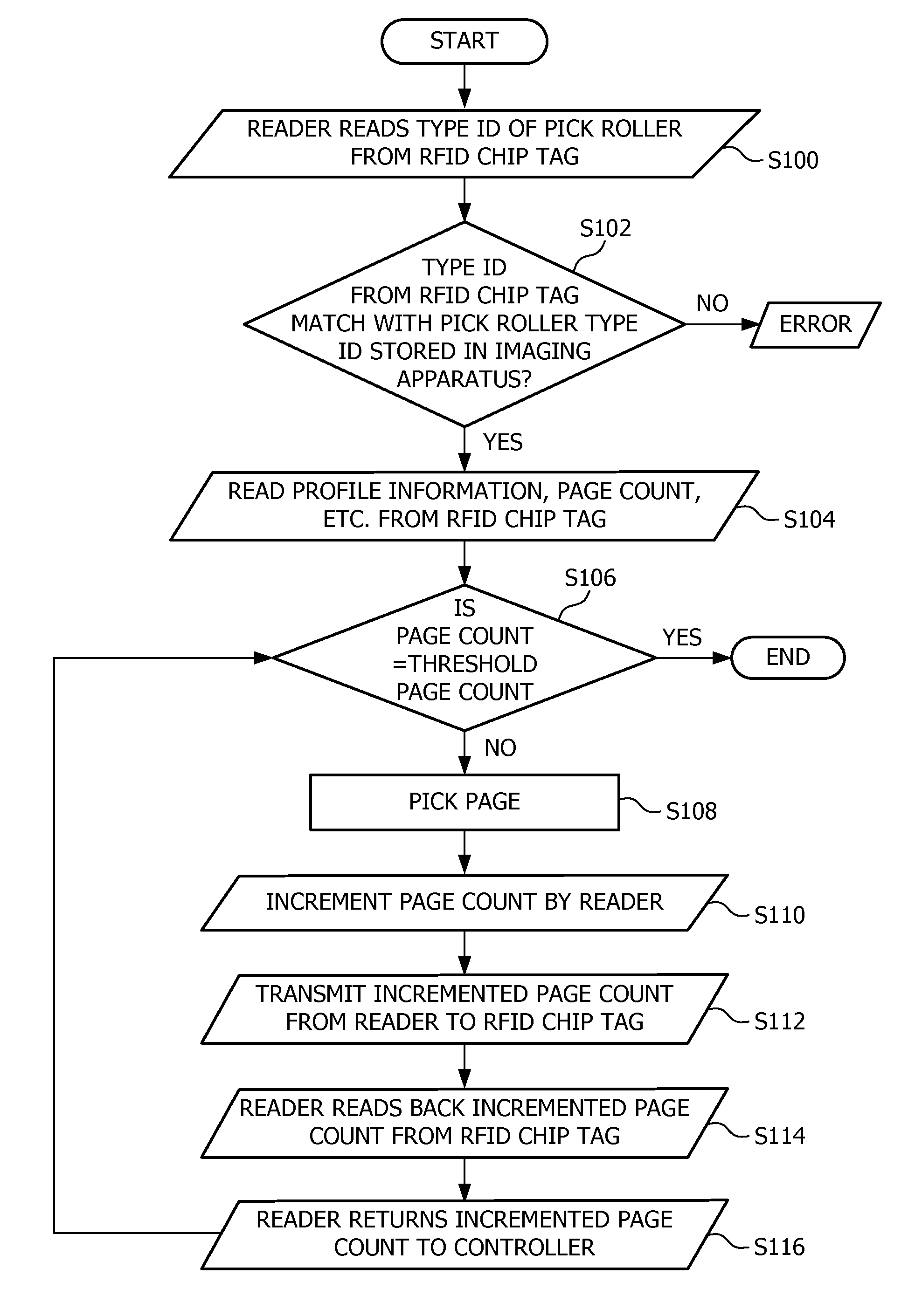
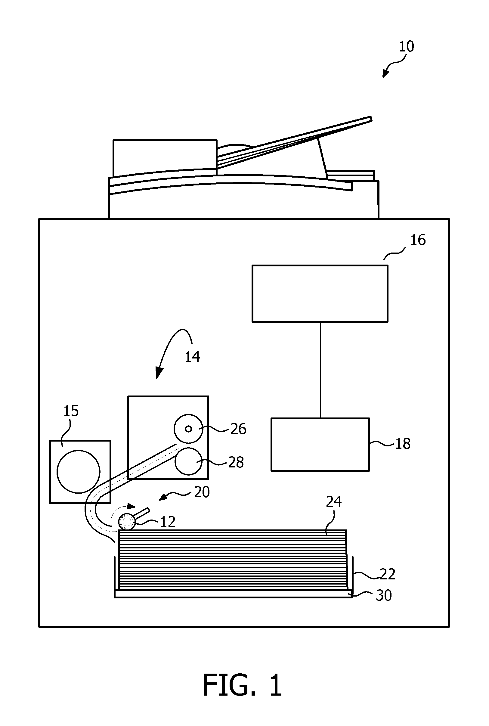
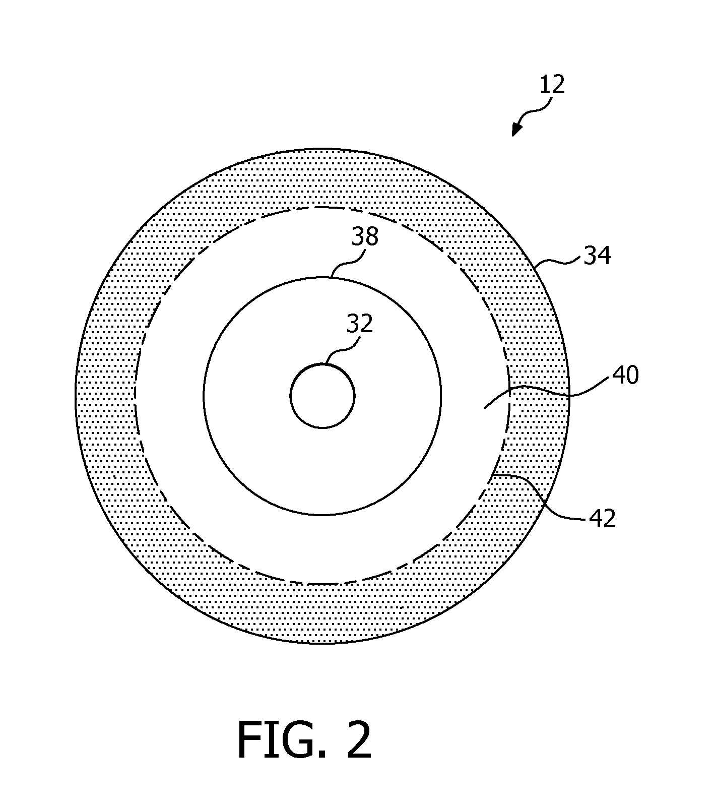
[0010]Exemplary embodiments of the present invention utilize RFID tags embedded in the wearable components in order to track the usage thereof in systems such as an image forming apparatus, and indicate when or whether the wearable components require replacement. RFID tags are widely used today for various purposes such as identification and location tracking An RFID tag typically includes two components—an integrated circuit chip with memory for storing information and an antenna that allows the chip to wirelessly communicate information with a reader, also known as interrogator. An RFID tag needs to be placed in relative proximity with the reader for communicating data therewith. RFID tags can be active or passive in nature. Active RFID tags have their own ...


PUM

PropertyMeasurementUnit
conductiveaaaaaaaaaa
depthaaaaaaaaaa
signal strengthaaaaaaaaaa

Abstract

An imaging apparatus having RFID tags associated with wearable components of a system to track the usage and wear levels of the wearable components. The RFID tags can be antennas formed from conductive material impregnated in the wear components such that the RFID tags are worn with the wearing of the wear components. The RFID tags may also be RFID chip tags having memory for storing information, a portion of which is updated in real time. The presence or absence of the impregnated antenna RFID tags or the updated information stored in the chip tags may be used to track usage and wear level of the wear components.

Description

BACKGROUND OF THE INVENTION[0001]1. Field of the Invention[0002]The present invention relates generally to radio frequency identification (RFID) tags and particularly to use of RFID tags disposed in wearable components of an imaging apparatus to detect the deterioration thereof.[0003]2. DESCRIPTION OF THE RELATED ART[0004]An imaging apparatus, such as a printer, a copier, or a multi-function printing device (MFP) typically includes wearable components such as tires, rollers, and belts that wear and / or deteriorate over the life of the imaging apparatus due to extensive use. The wearing of these wearable components may have a significant impact on the performance of the imaging apparatus. For example, wearing of pick tires and wear strips has been seen to significantly affect the reliability of picking sheets of media in an imaging apparatus. The wearing of fuser rollers has been seen to significantly affect media jam rates in the imaging apparatus. Some of these wearable components c...

Claims


Application Information

Patent Timeline
Patent Type & Authority Applications(United States)
IPC IPC(8): G01K7/01
CPCG03G21/1657G03G15/553
Inventor CHAPMAN, DANNY KEITHSCHOEDINGER, KEVIN DEANUNDERWOOD, MARK STEPHEN
Owner LEXMARK INT INC
Why Eureka
Try Eureka