Ultrasonic sensor and electronic device

a technology which is applied in the field of ultrasonic sensor and electronic device, can solve the problems of increasing the output voltage of the amplifier, reducing the sensing accuracy of the received signal, so as to achieve the effect of simplifying the configuration

Active Publication Date: 2011-10-27
SEIKO EPSON CORP
View PDF4 Cites 23 Cited by
  • Summary
  • Abstract
  • Description
  • Claims
  • Application Information

AI Technical Summary

Benefits of technology

[0008]Specifically, in an ultrasonic sensor, when ultrasound is output from a transmitter element and the ultrasound that is reflected by an object such as a detection subject is subsequently input to a receiver element, the ultrasound experiences attenuation and reduced sound pressure with greater distance from the transmitter element to the object and greater distance from the object back to the receiver element. Such attenuation of ultrasound and reduced sound pressure is observed in reflection by objects as well. Thus, the ultrasound input to the receiver element will have lower sound pressure as compared with the ultrasound that was output by the transmitter element, and for this reason it is typical practice to connect an amplifier to the receiver element, and to detect the received signal based on ultrasound input to the receiver element once the signal has been amplified by the amplifier.
[0030]Whereas the prior art relied on providing an oscillation isolation member discussed above, according to the present invention, the necessity of providing such an oscillation isolation member is obviated, and accordingly the configuration can be simplified, making possible application in devices requiring compact size, such as biological testing devices, for example.

Problems solved by technology

However, because oscillation of the transmitter element during ultrasound transmission is greater than oscillation of the receiver elements during ultrasonic wave reception, oscillation noise cannot be eliminated to a sufficient extent, and the resultant problem is diminished sensing accuracy of the received signal.
For this reason, it was difficult to distinguish between oscillation noise and a received signal produced by ultrasound reflected by an object, resulting in diminished sensing accuracy of received signals.
Therefore, if oscillation noise is input to the amplifier, there is a risk of increased output voltage of the amplifier due to the amplified oscillation noise, resulting in increased energy consumption.
There are instances in which oscillation noise generated during the ultrasound transmission period reaches the receiver elements after the transmission period has elapsed.

Method used


Image

  • Ultrasonic sensor and electronic device
  • Ultrasonic sensor and electronic device
  • Ultrasonic sensor and electronic device

Examples


first embodiment

[0038]A first embodiment of the present invention is described below with reference to the drawings.

Configuration of Biological Testing Device

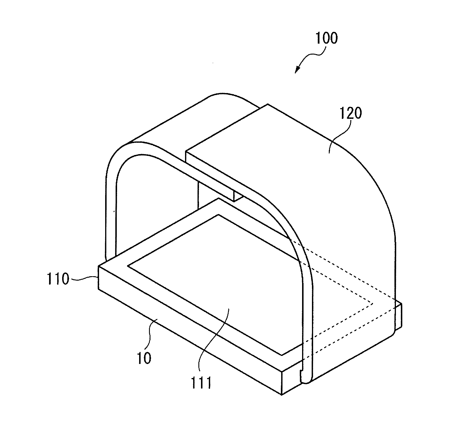
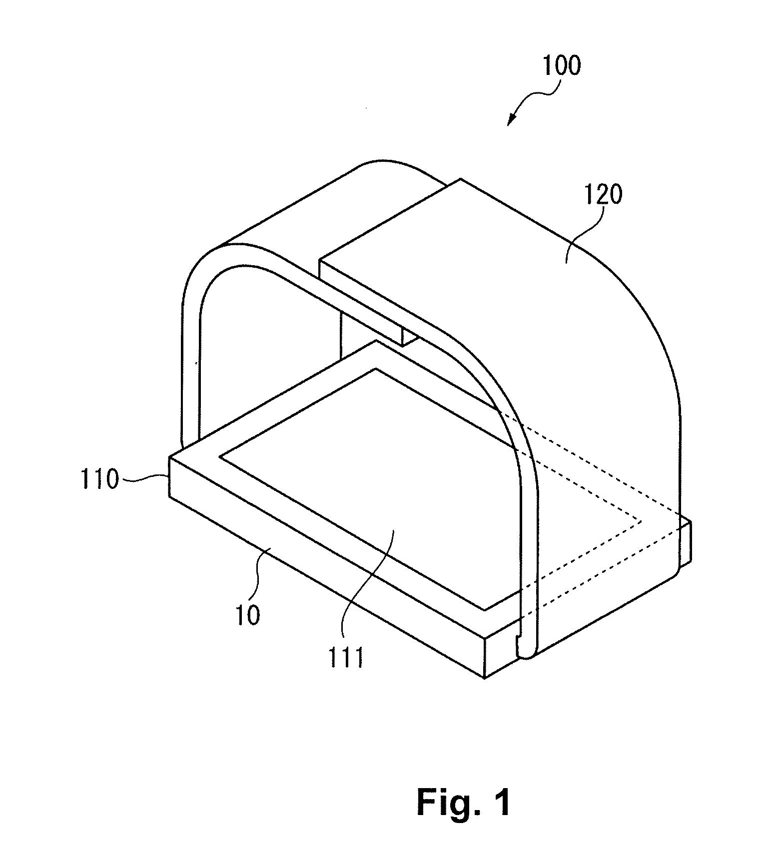
[0039]FIG. 1 is an exterior view showing a biological testing device 100 as an electronic device according to a first embodiment of the invention.

[0040]As shown in FIG. 1, the biological testing device 100 is a device designed to attach to a human finger using a band 120. The biological testing device 100 includes a device main unit 110, and the band 120 which is used to attach the device main unit 110 to the finger. The biological testing device 100 is also provided with an ultrasonic sensor 10.

[0041]This biological testing device 100 is designed, for example, to be arranged with the finger contacting a contact surface 111, and to transmit ultrasound to the finger from the ultrasonic sensor 10 as well as to receive ultrasound that is reflected from biological structures, such as blood vessels inside the finger, for example, for the purpose of...

second embodiment

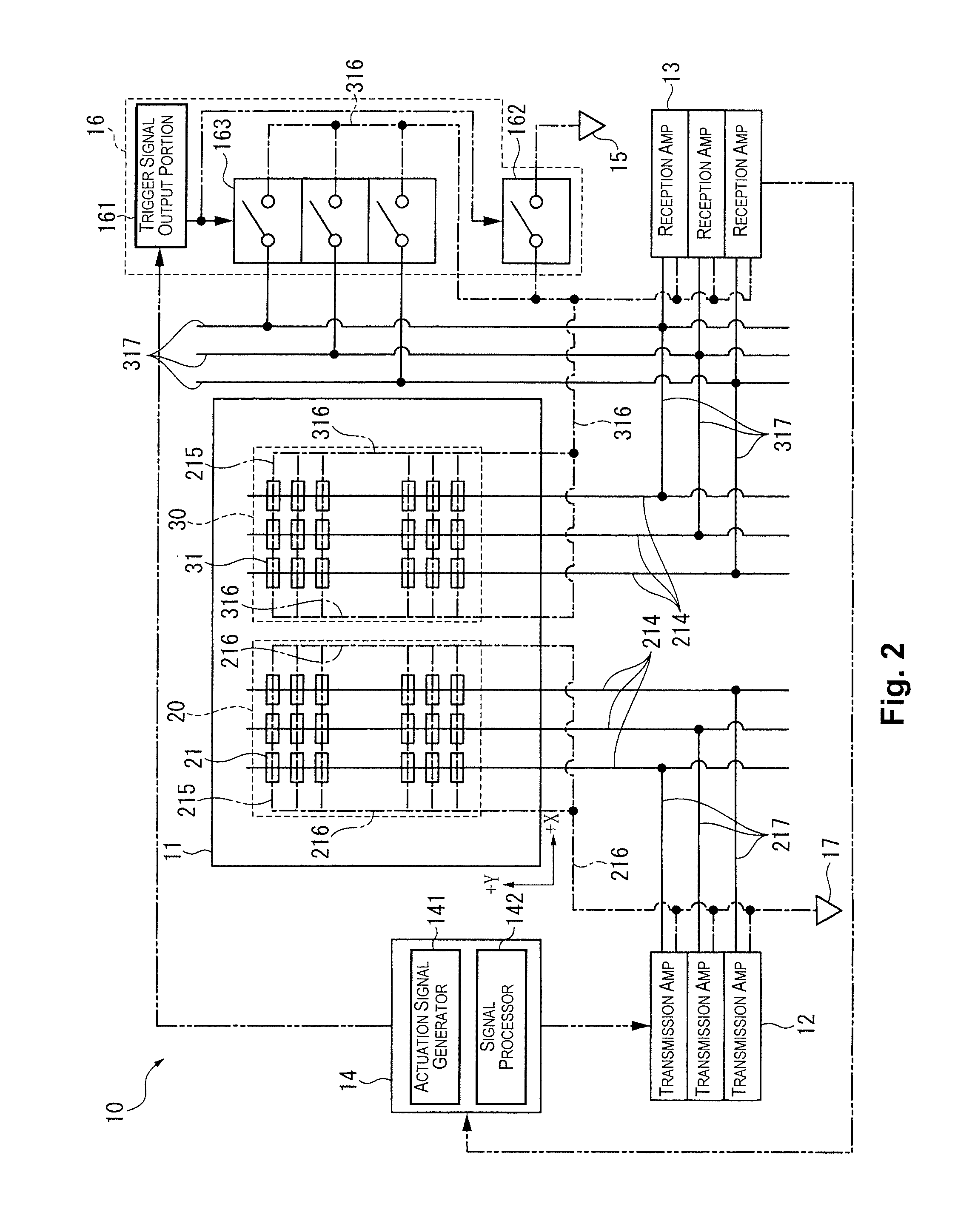
[0104]FIG. 6 is a circuit block diagram depicting in model form an ultrasonic sensor 10 in a second embodiment.

[0105]The differences are that, whereas according to the preceding first embodiment, the connection switching unit 16 has a configuration provided with the potential control switch 162 and the short switch 163, the potential controller 16 according to the second embodiment is provided with a first switch 164 and a second switch 165 in place of the short switch 163; and the potential controller 15 is provided with a first potential controller 18 and a second potential controller 19 respectively connected to the first switch 164 and the second switch 165.

[0106]The first switch 164 has a configuration comparable to the potential control switch 162 in the preceding embodiment, and is adapted to switch the connection state of the first potential controller 18 and the reception detection electrode lines 317 connected to the lower electrodes 3132.

[0107]The second switch 165 has a ...


PUM


Abstract

The ultrasonic sensor includes, on the same substrate, transmitter elements, receiver elements, a potential controller for receiver electrodes of the receiver elements, and a connection switching unit for the receiver electrodes and the potential controller. During the ultrasound transmission period of the transmitter elements, the connection switching unit connects the potential controller and the receiver electrodes. During the reception period of the receiver elements, the connection switching unit disconnects the potential controller and the receiver electrodes.

Description

CROSS-REFERENCE TO RELATED APPLICATIONS[0001]This application claims priority to Japanese Patent Application No. 2010-101774 filed on Apr. 27, 2010. The entire disclosure of Japanese Patent Application No. 2010-101774 is hereby incorporated herein by reference.BACKGROUND[0002]1. Technical Field[0003]The present invention relates to an ultrasonic sensor and to an electronic device.[0004]2. Related Art[0005]One type of ultrasonic sensor known in the prior art has a transmitter element for transmitting ultrasonic waves to a detection subject, and receiver elements for receiving ultrasonic waves reflected from the detection subject, the elements being disposed in an array on the same substrate (see Japanese Laid-Open Patent Application Publication No. 2009-225419, for example).[0006]The ultrasonic sensor disclosed in Japanese Laid-Open Patent Application Publication No. 2009-225419 is provided with an oscillation isolation member for compartmentalizing the transmitter element which tran...

Claims


Application Information

Patent Timeline
Patent Type & Authority Applications(United States)
IPC IPC(8): A61B8/00
CPCA61B8/06A61B8/4227A61B8/4455A61B8/56B06B1/0629A61B8/5269G01S15/8915A61B8/02A61B8/04A61B8/42G10K11/004
Inventor KANO, KAZUYUKI
Owner SEIKO EPSON CORP
Why Eureka
Try Eureka