Methodology for modeling the fuel rod power distribution within a nuclear reactor core

a technology of nuclear reactor and power distribution, which is applied in the direction of nuclear elements, instruments, greenhouse gas reduction, etc., can solve the problems of cladding failure, insufficient accuracy of power distribution estimates, and affecting the insertion capability of control rods, etc., and achieve the effect of fast fluence correction

Active Publication Date: 2011-10-27
WESTINGHOUSE ELECTRIC CORP
View PDF5 Cites 13 Cited by
  • Summary
  • Abstract
  • Description
  • Claims
  • Application Information

AI Technical Summary

Benefits of technology

[0020]In contrast to some conventional methods, the method of this invention will completely do away with the pin power form factors. Instead, the method of this invention follows the exposure history of each fuel rod in the core, and, based on that real history, derives the fuel rod nuclear data, i.e. fuel pin cross-sections in a physics terminology (to represent the probability of neutron reaction such as absorption, fission, etc.). In the actual application, the fuel rod by rod true history is parameterized and represented by its burnup along with the fast fluence. As with most core design codes, these two parameters are calculated (followed) by simply doing a time integration of fuel rod power and local neutron flux followed from manufacture to the current core state. In order to get the fuel pin by pin cross-sections, a reference cross-section table is pre-generated at a pre-defined reactor operating condition, typically the hot full power level condition. For a given actual fuel rod history (burnup and fast fluence), the fuel pin by fuel pin cross sections are derived through looking at the cross-section table and performing a fast fluence correction by comparing actual fluence with the reference one. During generation of the reference pin by pin cross-section table, a reference fuel pin flux form factor table is created as well. The method of this invention uses these pre-generated reference fuel pin flux form factors, in conjunction with the above fuel pin by fuel pin cross sections, to generate the actual pin flux form factors for the given history. The real time adjustment of the fuel pin flux form factors from the reference to the actual value using the fuel pin cross sections is based upon the fundamental theory of reactor physics by the nuclear design codes. Therefore, the fuel pin's history has been taken into account in both fuel pin cross sections and fluxes described above. Multiplying the fuel pin cell kappa-fissions and the fluxes will provide the fuel pin power distribution.

Problems solved by technology

This assists in retarding guide tube deformation under accident conditions which could detrimentally affect control rod insertion capability.
Under that type of condition the heat transfer from the fuel rod (66) to the adjacent coolant deteriorates raising the temperature of the fuel rod which can result in cladding failure.
The accuracy of these estimates is not considered high enough due to inherent approximations in the geometric model of the system and the nuclear cross-section databases that they employ.
Unfortunately, the real operational history of each fuel assembly is not known in advance, which makes it difficult to generate the right form factors to accurately simulate the core.
In order to capture the real history effect on fuel rod pin power, the prior art has tried many kinds of corrections to the pin power form factors with very complicated calculations employed to generate the fuel assembly data.
However, the results are still far from satisfactory, especially when control rod or gray rod insertion and withdrawal is commonly experienced during normal power operation.
This becomes a big and very difficult issue in the design of BWR cores and new designs of PWR cores, such as the AP1000 currently offered by Westinghouse Electric Company LLC.
These problems arise because it is not known in advance when, where, and in which assemblies the control rods will be inserted.
The history used to reflect the assembly data generated for the core design may be quite different from the real fuel history experienced in the core during normal operation and this difference is hard to capture in the core design codes using conventional methods.

Method used


Image

  • Methodology for modeling the fuel rod power distribution within a nuclear reactor core
  • Methodology for modeling the fuel rod power distribution within a nuclear reactor core
  • Methodology for modeling the fuel rod power distribution within a nuclear reactor core

Examples


Embodiment Construction

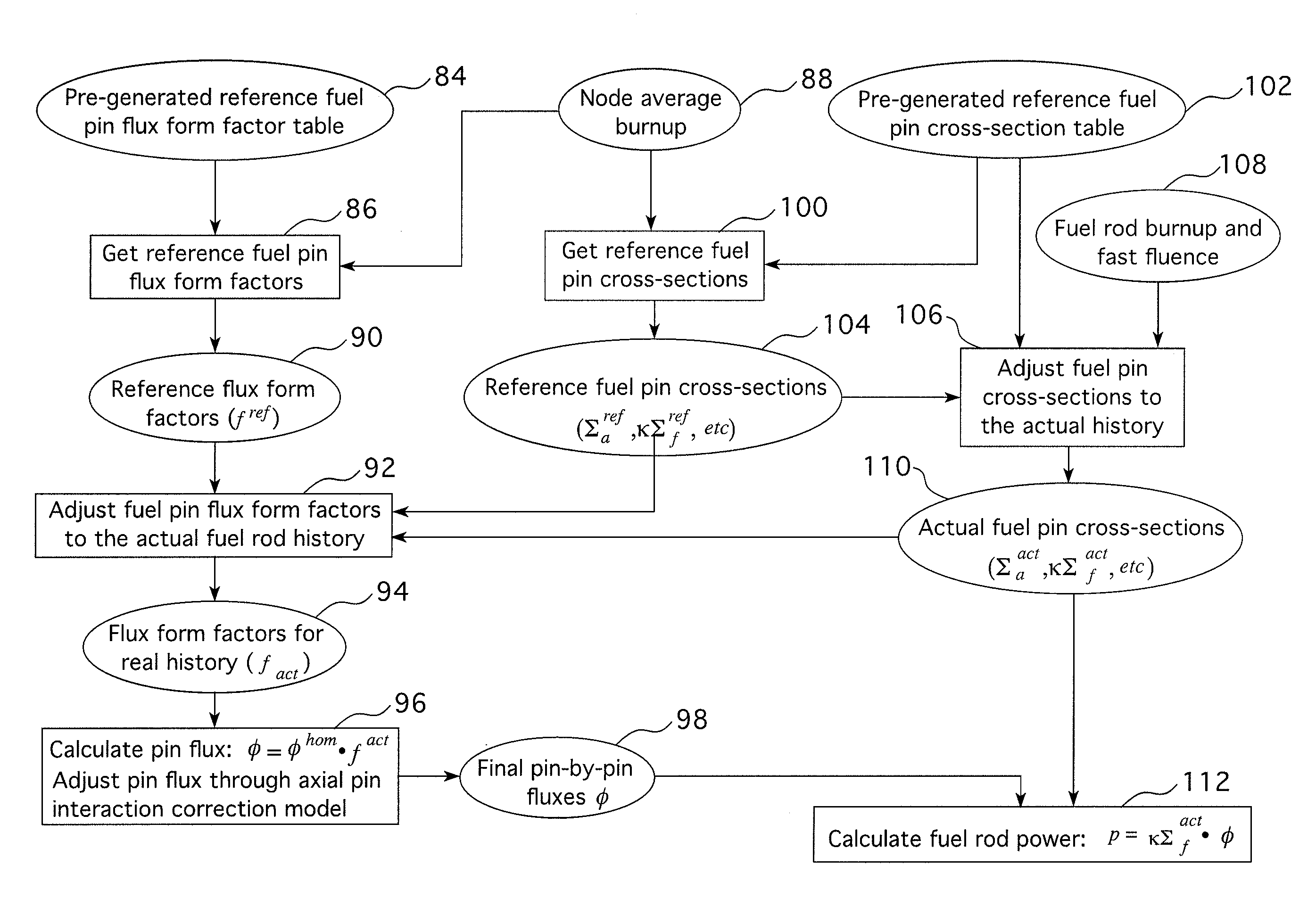
[0028]In most nuclear core design codes, such as ANC, to obtain the pin power distribution of each fuel rod, the fuel pin power form factors are applied to a homogeneous pin power profile over a node to get a pin by pin heterogeneous power distribution for the group of fuel assemblies within the node. It should be appreciated that “fuel rod” and “fuel pin” are used interchangeably in this description. As in many advanced nuclear core design codes, ANC uses energy group dependent form factors. That is, a given set of form factors corresponds to a number of fuel rods within a given energy range. The fuel rod (pin) power of each energy group (g) at (x,y) is expressed as:

Pg(x,y)=κΣf,ghom(x,y)·φghom(x,y)·fgp(x,y)=Pghom(x,y)·fgP(x,y)  (1)

Here (x, y) is the homogeneous pin power, which is obtained from the homogeneous pin-by-pin fluxes and kappa-fissions (ΛΣf, i.e. energy release rate from fission). The homogeneous pin fluxes φghom(x, y) are derived by solving two energy group diffusion eq...


PUM


Abstract

A method for modeling a nuclear reactor core that follows the history of each fuel pin and employs fuel pin flux form factors to explicitly track each fuel pin's fluence and burnup along its axial length and uses this information to obtain fundamental data for each fuel rod, i.e. fuel rod cross-sections, for each fuel pin segment. The data obtained for the fuel pins segments are employed to adjust the fuel pin flux form factors to match the real fuel pins' history so that the fuel rod power distribution can be precisely calculated based on the fuel rod cross-sections and the flux form factors.

Description

CROSS REFERENCE TO RELATED APPLICATION[0001]This application is a continuation-in-part of application Ser. No. 12 / 029,005, filed Feb. 11, 2008.BACKGROUND OF THE INVENTION[0002]1. Field of the Invention[0003]The present invention relates generally to a method of modeling the power distribution within the core of a nuclear reactor and more particularly to a method for designing initial and reload cores for a nuclear reactor.[0004]2. Description of the Prior Art[0005]The primary side of nuclear reactor power generating systems which are cooled with water under pressure comprises a closed circuit which is isolated and in heat-exchange relationship with a secondary side for the production of useful energy. The primary side comprises the reactor vessel enclosing a core internals structure that supports a plurality of fuel assemblies containing fissile material, the primary circuit within heat exchange steam generators, the inner volume of a pressurizer, pumps and pipes for circulating pre...

Claims


Application Information

Patent Timeline
Patent Type & Authority Applications(United States)
IPC IPC(8): G06F17/10G06G7/48
CPCY02E30/40G21D3/001Y02E30/00Y02E30/30
Inventor ZHANG, BAOCHENG
Owner WESTINGHOUSE ELECTRIC CORP
Why Eureka
Try Eureka