Manufacturing method of hermetic container and image display apparatus

a manufacturing method and technology of an image display device, applied in the manufacture of electrode systems, electric discharge tubes/lamps, semiconductor/solid-state device details, etc., can solve the problems of reducing the reliability of air tightness and joining strength, and achieve the effect of reducing the viscosity of the sealing material in the boundary region of the sealing material and reducing the viscosity of the sealing material on the unsealed portion

Inactive Publication Date: 2011-11-03
CANON KK
View PDF2 Cites 20 Cited by
  • Summary
  • Abstract
  • Description
  • Claims
  • Application Information

AI Technical Summary

Benefits of technology

[0012]According to the present invention, the local heating light is irradiated to the second region (unsealed portion) adjacent to the first region (sealed portion) on which the local heating light is irradiated, during the period that the viscosity of the sealing material at the portion (sealing material boundary region) of the sealed portion adjacent to the boundary between the sealed portion and the unsealed portion is equal to or lower than 1018 Pa·sec. Thus, although the viscosity of the sealing material on the u

Problems solved by technology

However, as illustrated in FIG. 7B, when local heating light 58 is scanned along a sealing material to obtain a hermetic container having continuous and closed sealing

Method used


Image

  • Manufacturing method of hermetic container and image display apparatus
  • Manufacturing method of hermetic container and image display apparatus
  • Manufacturing method of hermetic container and image display apparatus

Examples


example 1

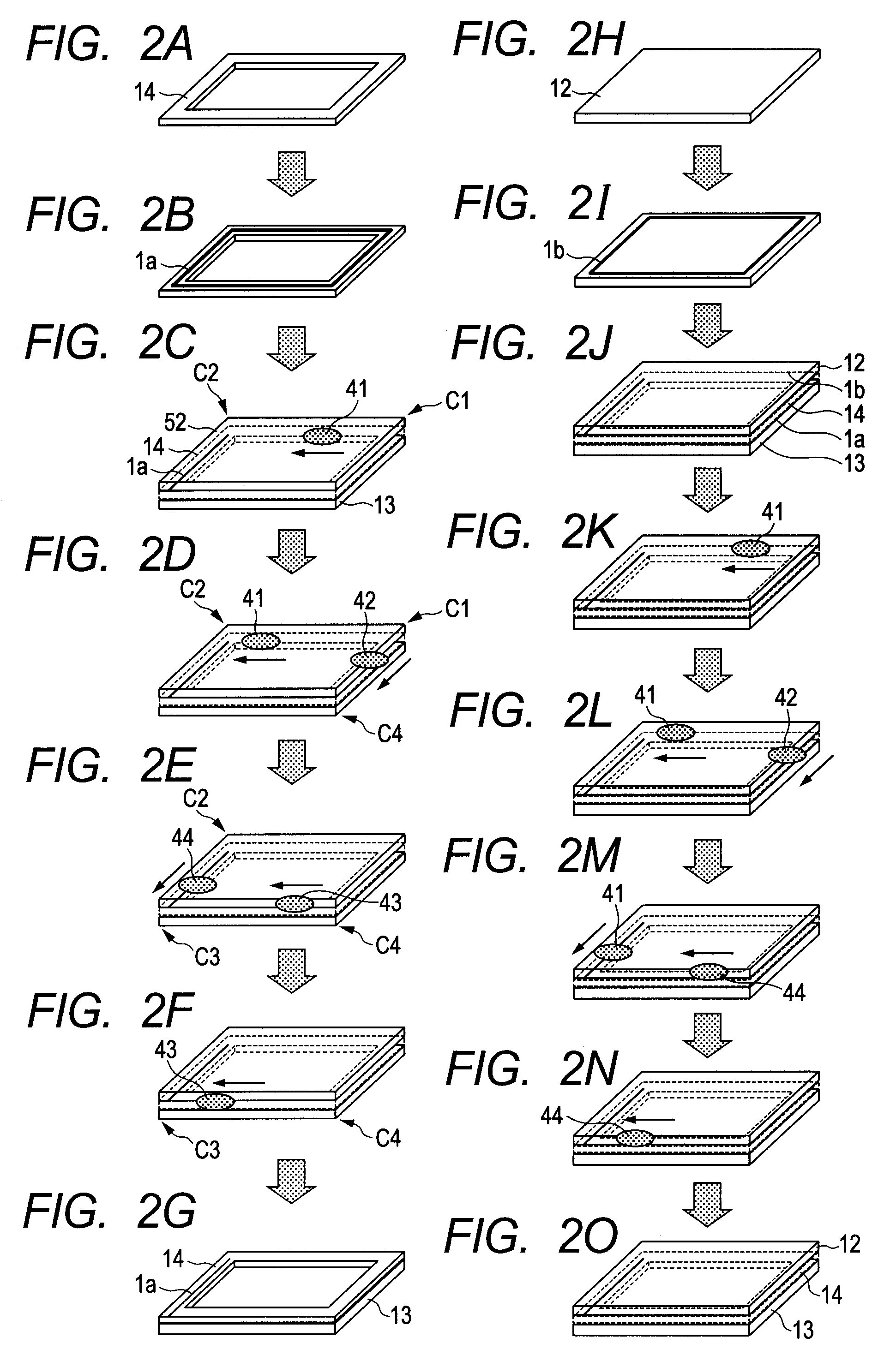
[0046]By applying the above-described embodiment, the frame member was hermetically sealed to the rear plate, and the frame member was hermetically sealed further to the face plate, whereby the vacuum hermetic container was manufactured.

[0047](Step 1)

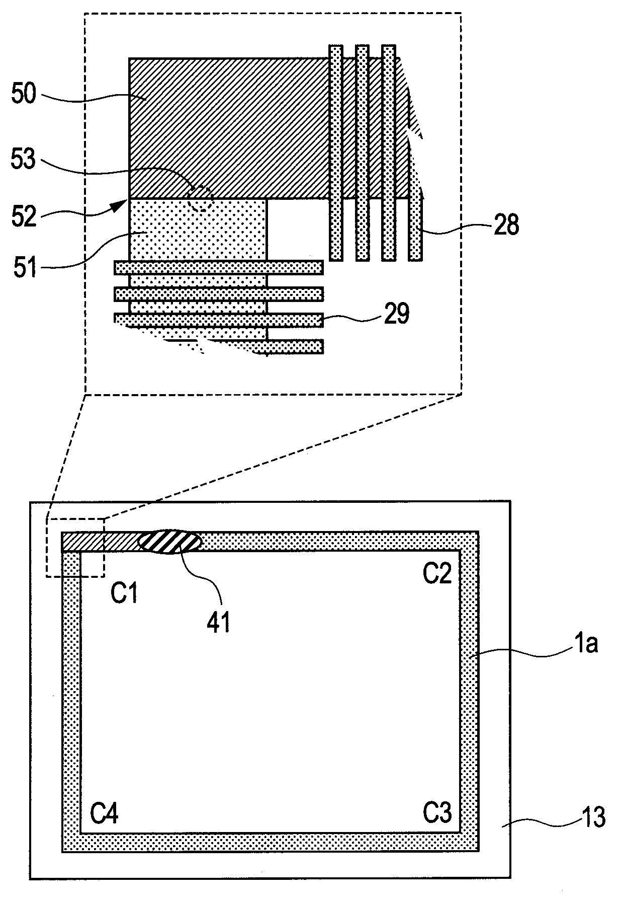
[0048]First, the face plate 14 was formed. More specifically, a high strain point glass substrate having the thickness of 1.5 mm (PD200: manufactured by Asahi Glass Co., Ltd.) was cut out to have an external shape of 980 mm×580 mm×1.5 mm. Then, a region of 970 mm×570 mm×1.5 mm at the central portion was cut out by cutting work, and the frame member 14 of which the cross sectional surface was almost rectangle having a width of 5 mm and a height of 1.5 mm was formed. Subsequently, the surface of the frame member 14 was degreased by organic solvent cleaning, pure water rinsing and UV-ozone cleaning.

[0049]Next, the sealing material 1a was formed on the frame member 14 so that the sealing material 1a was arranged at the center of the width d...


PUM

PropertyMeasurementUnit
Viscosityaaaaaaaaaa
Viscosityaaaaaaaaaa
Viscosityaaaaaaaaaa

Abstract

A manufacturing method of a hermetic container includes the steps of sandwiching a frame-like sealing material between a first glass substrate and a second glass substrate, irradiating first local heating light to a first region of the sealing material, and sealing the first glass substrate and the second glass substrate to each. The sealing is performed by irradiating, on a boundary between the first region of the sealing material and a second region of the sealing material which is adjacent to the first region and on which the first local heating light is not irradiated, second local heating light to heat and melt a portion of the second region adjacent to the boundary, during a period that viscosity of the sealing material at a portion of the first region adjacent to the boundary is equal to or lower than 1018 Pa·sec.

Description

BACKGROUND OF THE INVENTION[0001]1. Field of the Invention[0002]The present invention relates to a manufacturing method of a hermetic container and a manufacturing method of an image display apparatus, and more particularly, to a manufacturing method of an image display apparatus the inside of which is vacuumized and which has an electron-emitting device and a phosphor film.[0003]2. Description of the Related Art[0004]Image display apparatuses of a flat panel type such as an organic LED (light-emitting diode) display (OLED), a field emission display (FED), a plasma display panel (PDP), and the like are well known. Each of these image display apparatuses is manufactured by hermetically sealing glass substrates which face each other, and has a container in which an internal space is partitioned to an external space. To manufacture such a hermetic container, a spacing distance defining member, a local adhesive, and the like are arranged between the facing glass substrates as necessary,...

Claims


Application Information

Patent Timeline
IPC IPC(8): C03C27/00C03B29/00H01J9/26H01J11/46H01J11/48H01L51/50H05B33/04H05B33/10
CPCH01J9/261H01L51/5246H01J29/86H01J11/34H10K50/8426H01L23/02
Inventor MATSUMOTO, MAMOITO, NOBUHIRO
Owner CANON KK
Why Eureka
Try Eureka