Fuel preprocess system for coal combustion boiler

a preprocessing system and coal combustion boiler technology, applied in the direction of furnaces, combustion types, lighting and heating apparatuses, etc., can solve the problems of low boiler efficiency, low reaction temperature, and relatively low conversion ra

Active Publication Date: 2011-11-03
KOREA ELECTRIC POWER CORP
View PDF9 Cites 19 Cited by
  • Summary
  • Abstract
  • Description
  • Claims
  • Application Information

AI Technical Summary

Benefits of technology

[0008]The present invention provides a fuel preprocess system for coal combustion boiler that can reuse the primary air used in the drying process in the combustion of the boiler.

Problems solved by technology

These boilers, however, have relatively low reaction temperatures and thus have a relatively lower conversion than coal combustion boilers, and have a low boiler efficiency because of their small capacities.
However, in order to burn the above kinds of fuel completely or mixed with another kind of fuel in the conventional coal combustion boiler without replacing the pulverizer or burner, not only does the fuel supply equipment (transfer and storage equipment) need to be drastically modified, but the conventional pulverizer needs to be overdriven, thereby lowering the stability of the entire facility.
However, in applying a new pulverizer, a preprocess, such as drying, is needed in case the fuel contains a large amount of hemi-cellulose or moisture, making it difficult to apply the conventional system.

Method used


Image

  • Fuel preprocess system for coal combustion boiler
  • Fuel preprocess system for coal combustion boiler
  • Fuel preprocess system for coal combustion boiler

Examples


first embodiment

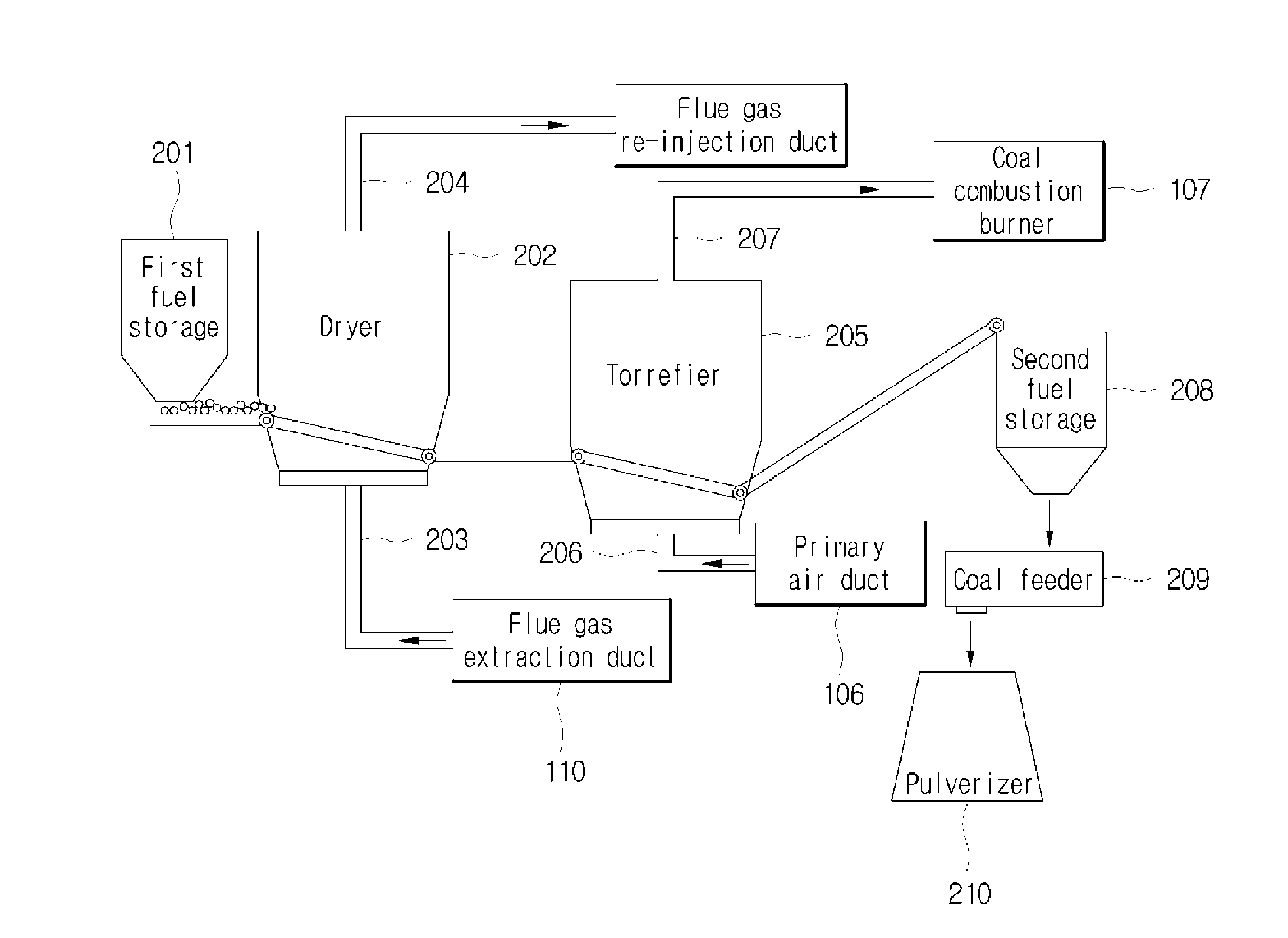
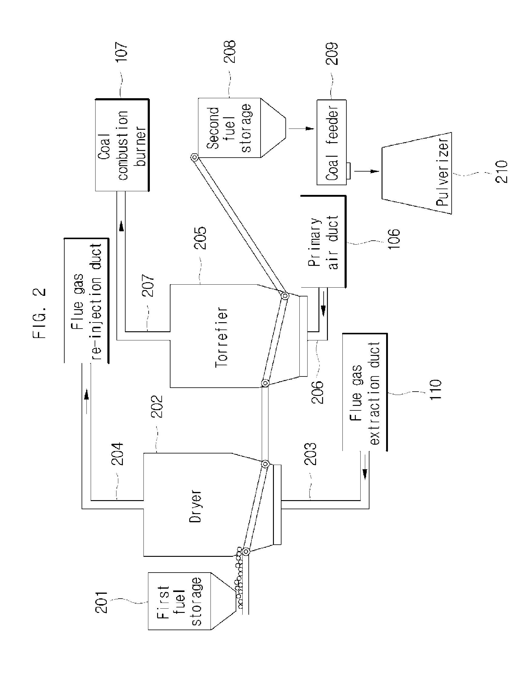
[0040]FIG. 2 is a diagram illustrating a fuel preprocess system for a coal combustion boiler in accordance with the present invention.

[0041]Referring to FIG. 2, the fuel preprocess system for a coal combustion boiler in accordance with a first embodiment of the present invention can include a first fuel storage 201, a dryer 202, a first heat source injector 203, a first vent 204, a torrefier 208, a second heat source injector 206, a second vent 207 and a second fuel storage 208.

[0042]Specifically, biomass or refuse-derived fuel can be stored in the first fuel storage 201.

[0043]The dryer 202 dries the biomass or refuse-derived fuel supplied by the first fuel storage 201. The dryer 202 performs a drying process by using the flue gas supplied by the flue gas extraction duct 110 at the rear end of the ID fan 109 shown in FIG. 1. Here, the dryer 202 can additionally include the first heat source injector 203.

[0044]The first heat source injector 203 can evenly supply the flue gas supplied...

second embodiment

[0053]FIG. 3 is a block diagram illustrating a fuel preprocess system for a coal combustion boiler in accordance with the present invention.

[0054]Referring to FIG. 3, the fuel preprocess system for a coal combustion boiler in accordance with a second embodiment of the present invention can include a first fuel storage 301, a dryer 302, a first dispersion plate 303, a first cyclone 305, a first vent 304, a torrefier 308, a second dispersion plate 309, first to fourth loop chambers 306, 307, 312, 313, a second cyclone 311, a second vent and a second fuel storage 314.

[0055]Specifically, biomass or refuse-derived fuel can be stored in the first fuel storage 301.

[0056]The biomass or refuse-derived fuel stored in the first fuel storage 301 is supplied to the dryer by transportation means such as a conveyer belt.

[0057]The dryer 302 is a fluidized bed dryer that dries the biomass or refuse-derived fuel by flow mixing the biomass or refuse-derived fuel. In order to dry the biomass or refuse-...


PUM


Abstract

A fuel preprocess system for a coal combustion boiler is disclosed. The fuel preprocess system for a coal combustion boiler that dries biomass or refuse-derived fuel in accordance with the present invention can include: a dryer configured to dry the biomass or refuse-derived fuel by use of flue gas generated after combustion in the boiler; and a torrefier configured to devolatilize a fibrous component contained in the dried fuel from the fuel dried in the dryer by use of primary air that is heat-exchanged after the combustion in the boiler.

Description

CROSS-REFERENCE TO RELATED APPLICATIONS[0001]This application claims the benefit of Korean Patent Application No. 10-2010-0039730, filed with the Korean Intellectual Property Office on Apr. 28, 2010, the disclosure of which is incorporated herein by reference in its entirety.BACKGROUND[0002]1. Technical Field[0003]The present invention is related to a fuel preprocess system for coal combustion boiler.[0004]2. Background Art[0005]In general, biomass or refuse-derived fuel is mainly used in a fluidized bed combustor and a stoker incinerator, which are relatively little affected by the size of fuel particles and the phase change, and is used to produce steam and electricity by use of the generated heat. These boilers, however, have relatively low reaction temperatures and thus have a relatively lower conversion than coal combustion boilers, and have a low boiler efficiency because of their small capacities.[0006]Accordingly, there have been a number of efforts to burn the biomass or re...

Claims


Application Information

Patent Timeline
Patent Type & Authority Applications(United States)
IPC IPC(8): F22B37/00
CPCF23G5/0276F23G5/04F23G5/50F23G7/10F23G2201/303F26B2200/02F23G2201/60F23G2206/10F23L2900/15043F26B3/08F23G2201/50C10L2290/02C10L2290/54C10L2290/06C10L5/442C10L5/46C10L9/083C10L2290/08Y02E50/10Y02E50/30
Inventor KIM, DONG-WONLEE, JONG-MINKIM, YOUNG-JOOKIM, JAE-SUNG
Owner KOREA ELECTRIC POWER CORP
Why Eureka
Try Eureka