Method for operating an hydraulic brake system in a motovehicle

a technology of hydraulic brakes and moto vehicles, which is applied in the direction of braking systems, braking components, transportation and packaging, etc., can solve the problems of energization and noise, and achieve the effect of simple and efficient manner and keeping the accompanying noise development as low

Inactive Publication Date: 2011-11-03
ROBERT BOSCH GMBH
View PDF24 Cites 1 Cited by
  • Summary
  • Abstract
  • Description
  • Claims
  • Application Information

AI Technical Summary

Benefits of technology

[0007]The present invention is based on the objective of raising the temperature in an hydraulic brake system of a vehicle in a simple and efficient manner, and to keep the accompanying noise development as low as possible at the same time.
[0008]The present invention is used for hydraulic vehicle brake systems having at least two electrically actuable hydraulic valves, especially electromagnetic valves, which are intermittently supplied with electrical energy for heating the hydraulic fluid, and for the lowering of the fluid viscosity that goes along with it, so that a more rapid pressure generation is able to be realized. According to the present invention, during a heating period for heating the hydraulic fluid, the hydraulic valves are energized simultaneously but, at least intermittently, at different current intensities. This procedure yields various advantages. Because of the simultaneous energization of at least two hydraulic valves, a relatively high energy input into the hydraulic fluid is obtained, together with correspondingly faster heating. The different current intensities by which the hydraulic valves are energized at least intermittently leads to a phase offset between the hydraulic valves, so that a noise development that goes along with a higher current intensity and is attributable to a mechanical actuation of this valve, in particular, also takes place at one valve only. The simultaneous electromechanical actuation of two hydraulic valves at one instant, which would cause higher noise development, is therefore avoided. Instead, the switching state of the hydraulic valves is changed in alternation, so that despite the fact that the number of individual noises rises over all, the noise level is still lower than in a simultaneous actuation of two valves.
[0010]Furthermore, it is possible to provide different energization profiles at which the hydraulic valves are energized for heating the hydraulic fluid. For example, it may be indicated to determine the instantaneous hydraulic fluid temperature with the aid of a temperature sensor and to specify different heating or energization profiles as a function of the instantaneous temperature level. For a rapid temperature rise, for instance, a current profile having a rapid sequence of high current pulses is initially applied at each hydraulic valve; these high current pulses may actually bring about a change in the mechanical switching state, but they accelerate the heating at the same time. According to the present invention, the high current pulses of different valves take place at a mutual phase offset in order to prevent the simultaneous opening or closing of two hydraulic valves, which would lead to greater noise.
[0012]The advantage of energizing the at least two hydraulic valves using different current intensities consists of the more homogenous energy transfer to the hydraulic fluid and the more uniform heating of the fluid that accompanies it.
[0013]According to one preferred specific embodiment, each hydraulic valve participating in the heating of the hydraulic fluid is acted upon by alternating phases of high and low current intensity. This advantageously prevents overheating of the hydraulic valves, because during the lower energization phase there is also less heat development. The energization peaks in the hydraulic valves advantageously lie at a mutual phase offset in order to avoid that mechanically caused noises during the change of the switching state of the hydraulic valves occur at the same time. However, in order to prevent cooling or flattening of the temperature rise of the hydraulic fluid in the meantime, it may be useful to have the phases of high current intensities in different hydraulic valves follow each other immediately, i.e., without any dead times between them. For one, this avoids the problem of increasing noise, while the high heat output in each hydraulic valve takes place in immediate succession for another, which leads to a more rapid temperature increase over all.
[0017]According to one further useful development, the energization is to be interrupted at least once in at least one hydraulic valve during one heating period. For one, this procedure has the advantage that it counteracts overheating of the hydraulic valve. For another, this also makes it possible to influence the pressure conditions in the brake circuit. For example, if the particular hydraulic valve is a reversing valve which controls the hydraulic supply in an hydraulic brake circuit, then a pressure release in the brake circuit is able to be achieved in a reversing valve that is open in a deenergized state. This procedure is useful in particular at low ambient temperatures, because an intake valve lying in the brake circuit opens more rapidly than the reversing valve due to a lower response time, so that pressure is locked in in the brake circuit and may have an undesired decelerating effect at the wheel brakes. By reducing the energization down to zero at the reversing valve and by the attendant opening of the reversing valve it is ensured that the enclosed pressure in the brake circuit is reduced and that an undesired decelerating effect at the wheel brakes is avoided.

Problems solved by technology

The energization is accompanied by noise, especially when the current pulse is large enough to switch the valve, that is to say, large enough to change the mechanical state of the valve.

Method used


Image

  • Method for operating an hydraulic brake system in a motovehicle
  • Method for operating an hydraulic brake system in a motovehicle
  • Method for operating an hydraulic brake system in a motovehicle

Examples


Embodiment Construction

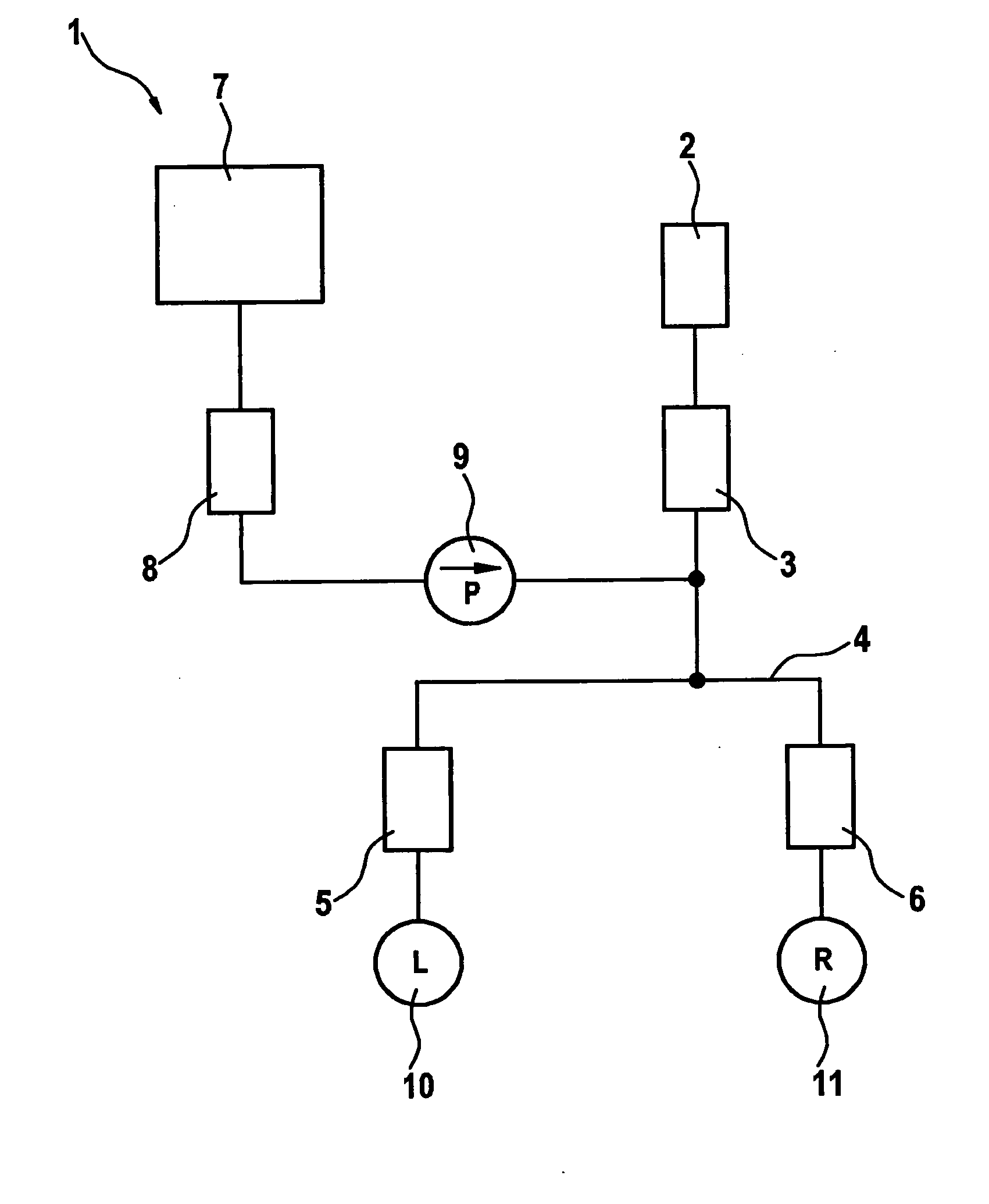
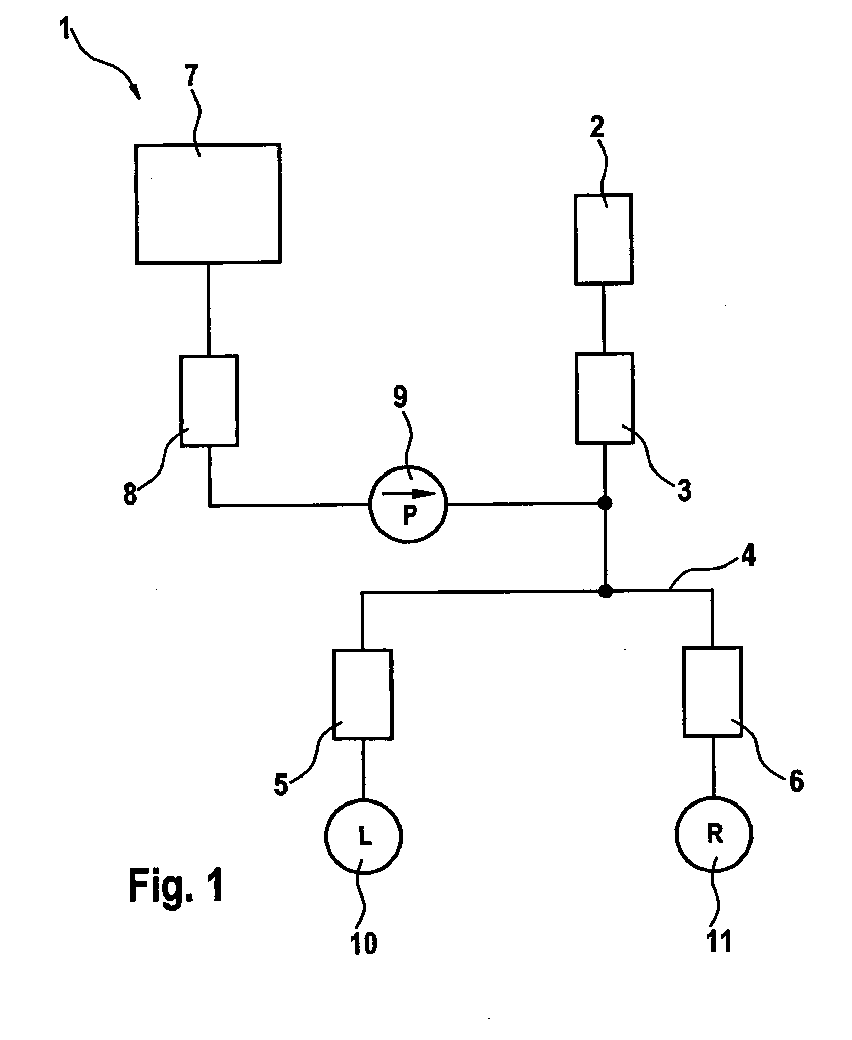
[0023]FIG. 1 shows a portion of an hydraulic brake system 1 for a motor vehicle, which includes wheel brake units 10 and 11 at, respectively, the left and right wheel of the vehicle. Brake system 1 has a main cylinder 2, which is actuated by the driver, and an electromagnetic hydraulic valve 3 postconnected to main cylinder 2, which functions as a reversing valve. Via a hydraulic valve 8 acting as high-pressure switching valve, and via a supply pump 9, hydraulic fluid from an hydraulic reservoir 7 is guided into brake circuit 4 for the supply of wheel brake units 10 and 11. Additional electromagnetic hydraulic valves 5 and 6, which act as intake valves, are connected upstream from wheel brake units 10 and 11 in brake circuit 4.

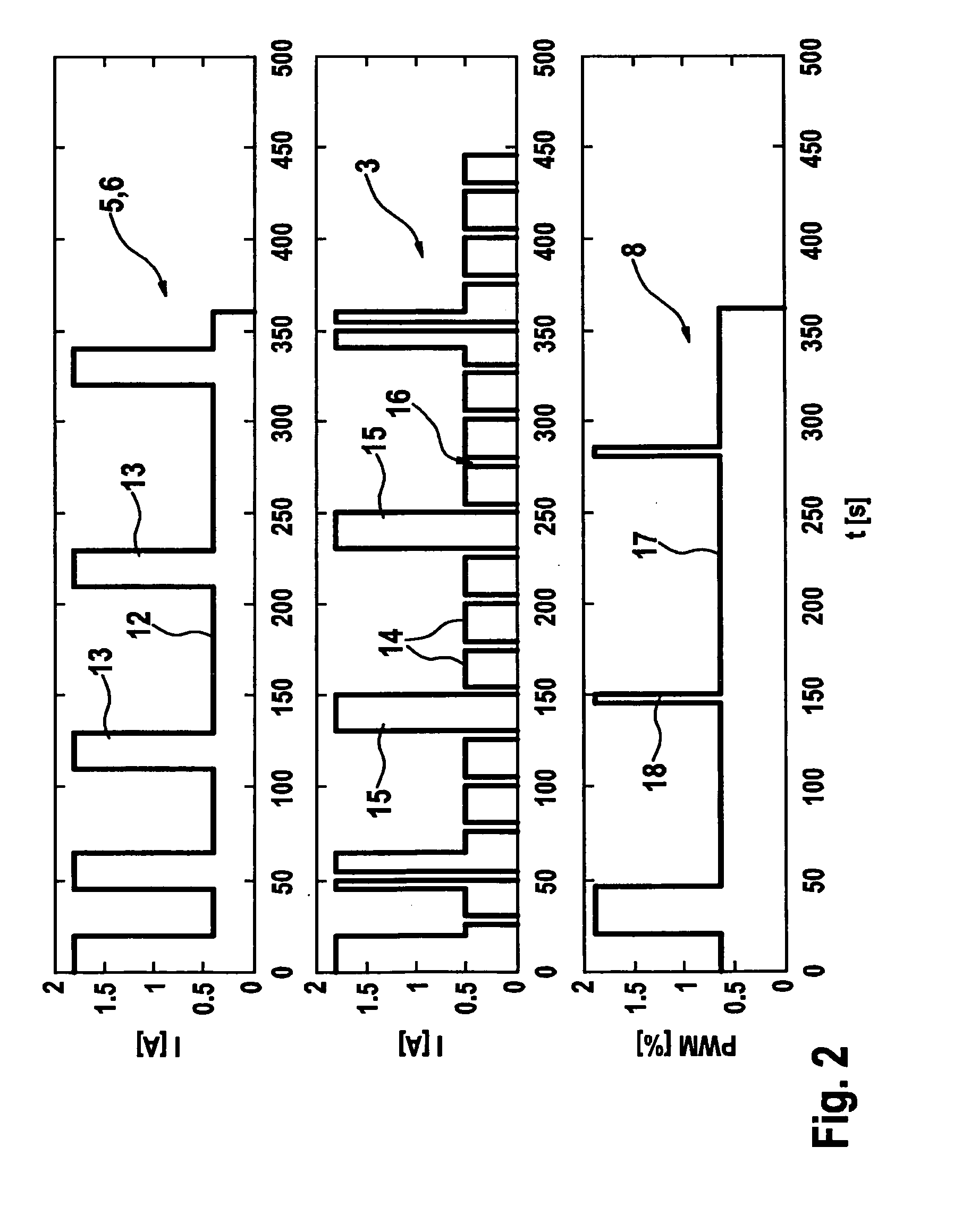
[0024]In order to heat the hydraulic fluid as quickly as possible especially at low outside temperatures, the different hydraulic valves are acted upon by phases of high and low current intensities during a heating period, which leads to heating of the hydraul...


PUM


Abstract

In a method for operating an hydraulic brake system in a vehicle, which has at least two electrically actuable hydraulic valves, the hydraulic valves are energized at a different current intensity at least intermittently in order to heat the hydraulic fluid during a heating period.

Description

BACKGROUND OF THE INVENTION[0001]1. Field of the Invention[0002]The present invention relates to a method for operating an hydraulic brake system in a vehicle.[0003]2. Description of Related Art[0004]From published German patent application document DE 10 2005 046 652 A1, a method is known for operating a brake system of motor vehicles, which is equipped with electrically controllable hydraulic valves, whose coils are energized at least intermittently in order to heat the hydraulic fluid contained in the hydraulic system. The energization is carried out when the temperature of the hydraulic fluid is below a threshold value. The energization takes place in two consecutive heating phases such that the coil temperature corresponds to a specified coil temperature value at the end of the first heating phase and the coil temperature is kept at least approximately constant during the second heating phase.[0005]From published German patent application document DE 101 63 524 A1, a method for...

Claims


Application Information

Patent Timeline
Patent Type & Authority Applications(United States)
IPC IPC(8): H05B1/00F15B21/0427
CPCB60T17/221B60T8/4872F15B21/042F15B2211/328F15B21/0427
Inventor LOEFFLER, THOMASREIZE, ANDREASKAESTNER, FRANKHUBER, SIEGFRIEDHUTT, MARKUS
Owner ROBERT BOSCH GMBH
Why Eureka
Try Eureka