Fault protection in voltage source converters with redundant switching cells via mechanical switches being closed pyrotechnically

a technology of mechanical switches and fault protection, applied in the field of voltage source converters, can solve problems such as the interruption of current path through the igbt, the failure of the switching assembly, and the stoppage of the source converter

Active Publication Date: 2011-11-03
ABB POWER GRIDS SWITZERLAND AG
View PDF4 Cites 24 Cited by
  • Summary
  • Abstract
  • Description
  • Claims
  • Application Information

AI Technical Summary

Benefits of technology

[0011]The object of the present invention is to provide a Voltage Source Converter of the type defined in the introduction, which is improved in at least some aspect with respect to the ability of handling failures of semiconductor chips thereof compared to such Voltage Source Converters already known.

Problems solved by technology

When all the semiconductor chips of the switching assembly have been consumed in this way operation of the Voltage Source Converter has to be stopped and the switching assembly failed has to be replaced.
However, after some period of time the current path through the IGBT will be interrupted due to temperature constrains thereon and jump to another semiconductor chip connected in parallel therewith.
With this type of series connection of the switching assemblies it may take an acceptably long time before all semiconductor chips of a switching assembly have been knocked out and operation of the converter has to be stopped, since the dimensioning of the current allowed through the converter is chosen so that this will take many years.

Method used


Image

  • Fault protection in voltage source converters with redundant switching cells via mechanical switches being closed pyrotechnically
  • Fault protection in voltage source converters with redundant switching cells via mechanical switches being closed pyrotechnically
  • Fault protection in voltage source converters with redundant switching cells via mechanical switches being closed pyrotechnically

Examples


Embodiment Construction

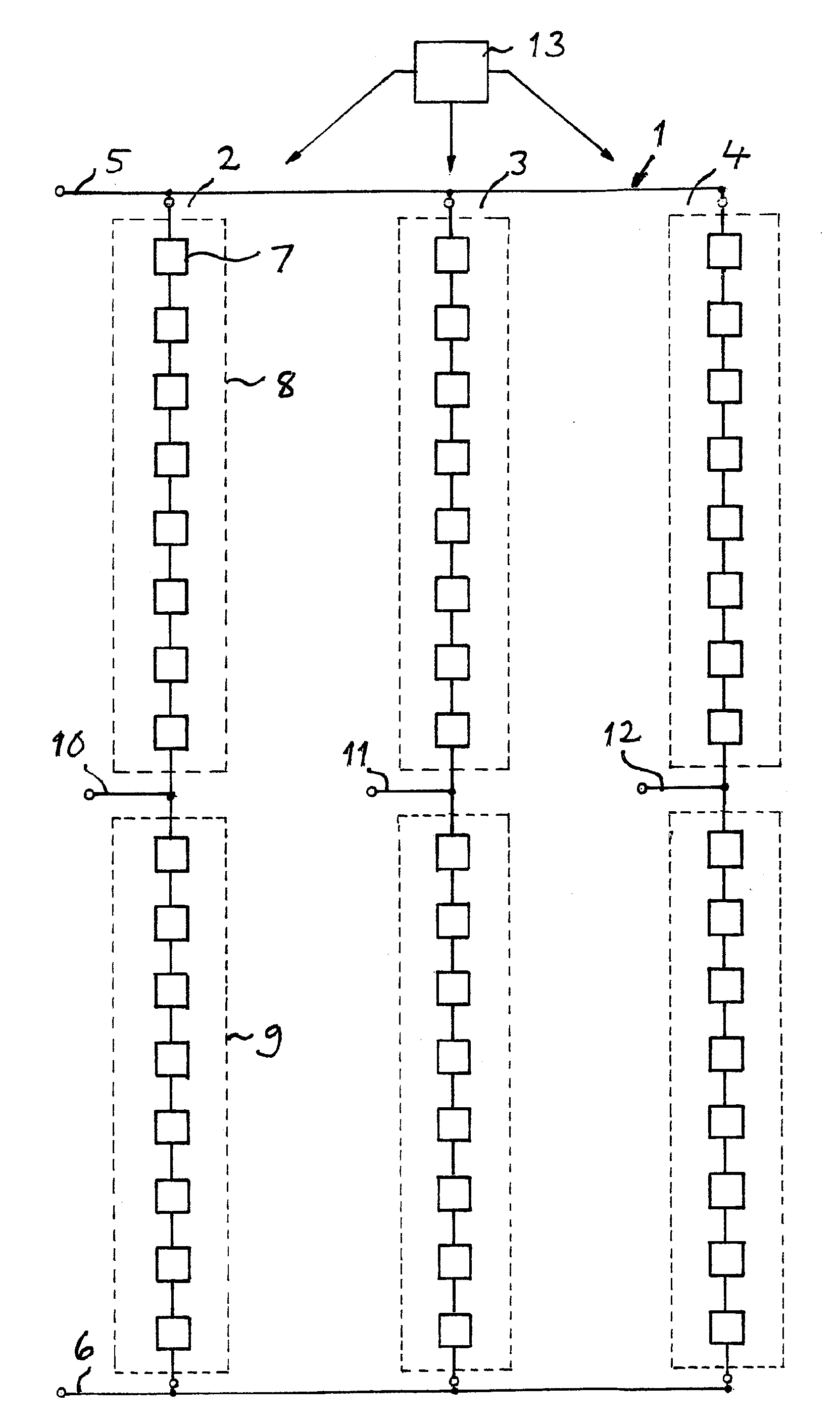
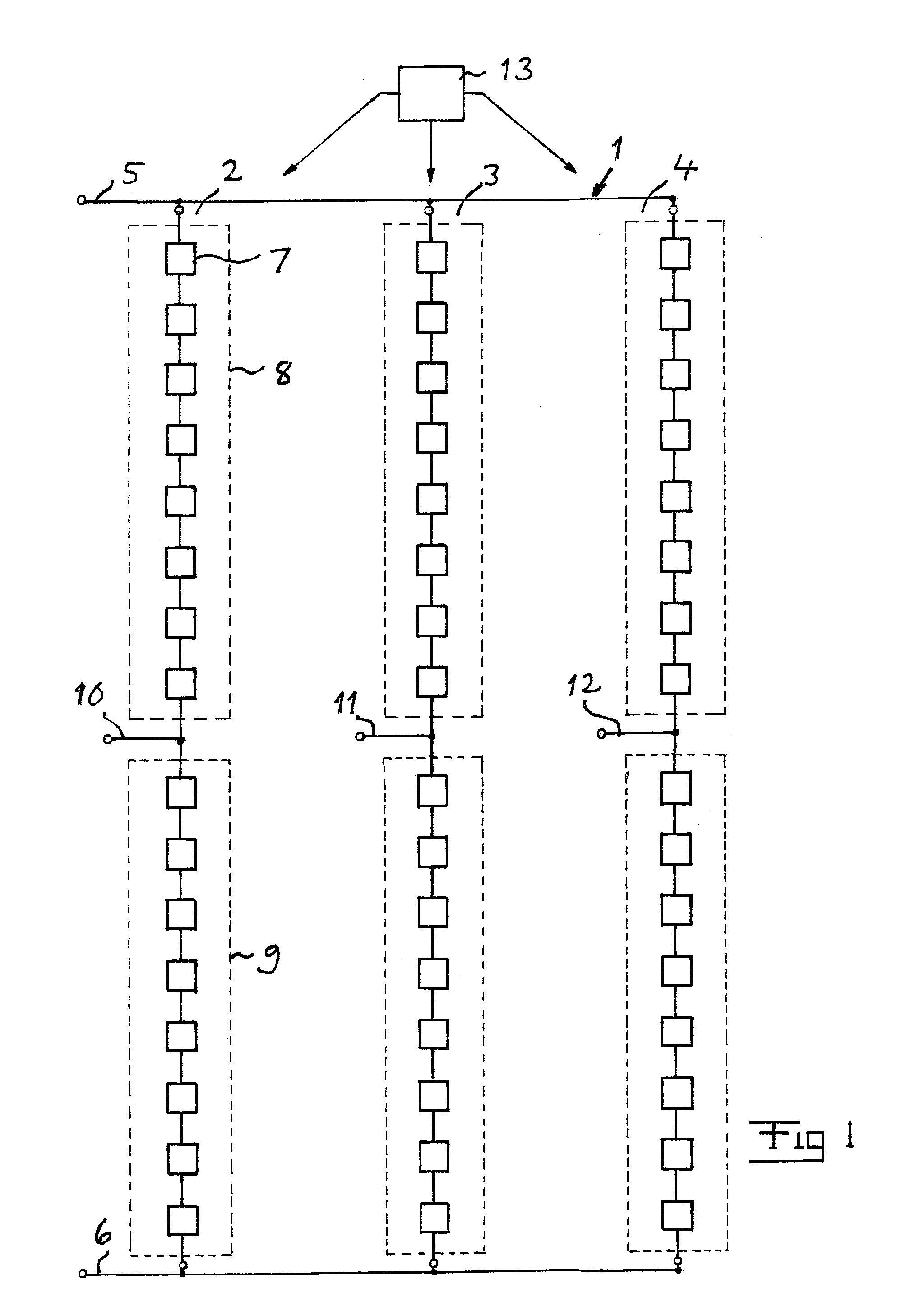
[0042]FIG. 1 illustrates very schematically the general construction of a Voltage Source Converter 1 of the type to which the present invention relates. This converter has three phase legs 2-4 connected to opposite poles 5, 6 of a direct voltage side of the converter, such as a direct voltage network for transmitting high voltage direct current. Each phase leg comprises a series connection of switching assemblies 7 indicated by boxes, in the present case 16 to the number, but this number may be much higher, such as 50, and there are some more than required for holding the voltage they have to hold together between said poles. This series connection is divided into two equal parts, an upper valve branch 8 and a lower valve branch 9, separated by a mid point 10-12 forming a phase output being configured to be connected to an alternating voltage side of the converter. The phase outputs 10-12 may possibly through a transformer connect to a three phase alternating voltage network, load, ...


PUM


Abstract

A Voltage Source Converter has a series connection of switching assemblies, in which each switching assembly has an electrically conducting plate member carrying a plurality of semiconductor chips each having at least a semiconductor device of turn-off and a free-wheeling diode connected in parallel therewith. Said chips are connected in parallel with each other by each being connected by at least one individual conductor member to a said plate member of an adjacent switching assembly of said series connection. Each switching assembly has a mechanical switch configured to be open under normal operation of the switching assembly and configured to enable connection of said plate member of the switching assembly to the plate member of an adjacent switching assembly for bypassing said semiconductor chips of the switching assembly to which the mechanical switch belongs in the case of occurrence of a short circuit current through a semiconductor chip of the switching assembly.

Description

TECHNICAL FIELD OF THE INVENTION AND BACKGROUND ART[0001]The present invention relates to a Voltage Source Converter having at least one phase leg connecting to opposite poles of a direct voltage side of the converter and comprising a series connection of switching assemblies, each switching assembly having an electrically conducting plate member carrying a plurality of semiconductor chips each having at least a semiconductor device of turn-off type and a free-wheeling diode connected in parallel therewith said chips being connected in parallel with each other by each being connected by an individual conductor member to a said plate member of an adjacent switching assembly of said series connection of switching assemblies, a midpoint of said series connection forming a phase output being configured to be connected to an alternating voltage side of the converter and to divide the phase leg into an upper valve branch and a lower valve branch.[0002]Such converters with any number of sa...

Claims


Application Information

Patent Timeline
Patent Type & Authority Applications(United States)
IPC IPC(8): H02H7/122
CPCH01H39/004H02M2007/4835H02M7/797H02M1/32H02M1/325H02M7/4835H01H39/00
Inventor ASPLUND, GUNNAR
Owner ABB POWER GRIDS SWITZERLAND AG
Why Eureka
Try Eureka