Turbine engine rotor wheel with blades made of a composite material provided with a spring ring

a technology of composite materials and turbine engines, which is applied in the direction of machines/engines, stators, liquid fuel engines, etc., can solve the problems of gas leakage between the tips of the blades and the casing, and the sealing between the rotor wheel and the casing no longer being provided properly

Active Publication Date: 2011-11-03
SN DETUDE & DE CONSTR DE MOTEURS DAVIATION S N E C M A
View PDF4 Cites 18 Cited by
  • Summary
  • Abstract
  • Description
  • Claims
  • Application Information

AI Technical Summary

Benefits of technology

[0008]A main object of the present invention is thus to mitigate such drawbacks by proposing a turbomachine rotor

Problems solved by technology

However, in operation (when hot), this clearance may give rise to leakage of gas between the tips of the blades and the casing.
As a result, when operating while hot, the radial clearance that is left on mounting between

Method used


Image

  • Turbine engine rotor wheel with blades made of a composite material provided with a spring ring
  • Turbine engine rotor wheel with blades made of a composite material provided with a spring ring
  • Turbine engine rotor wheel with blades made of a composite material provided with a spring ring

Examples


Embodiment Construction

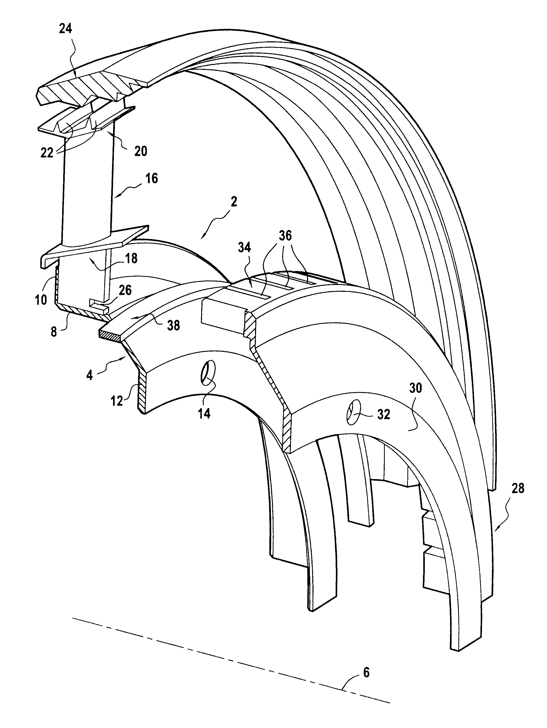
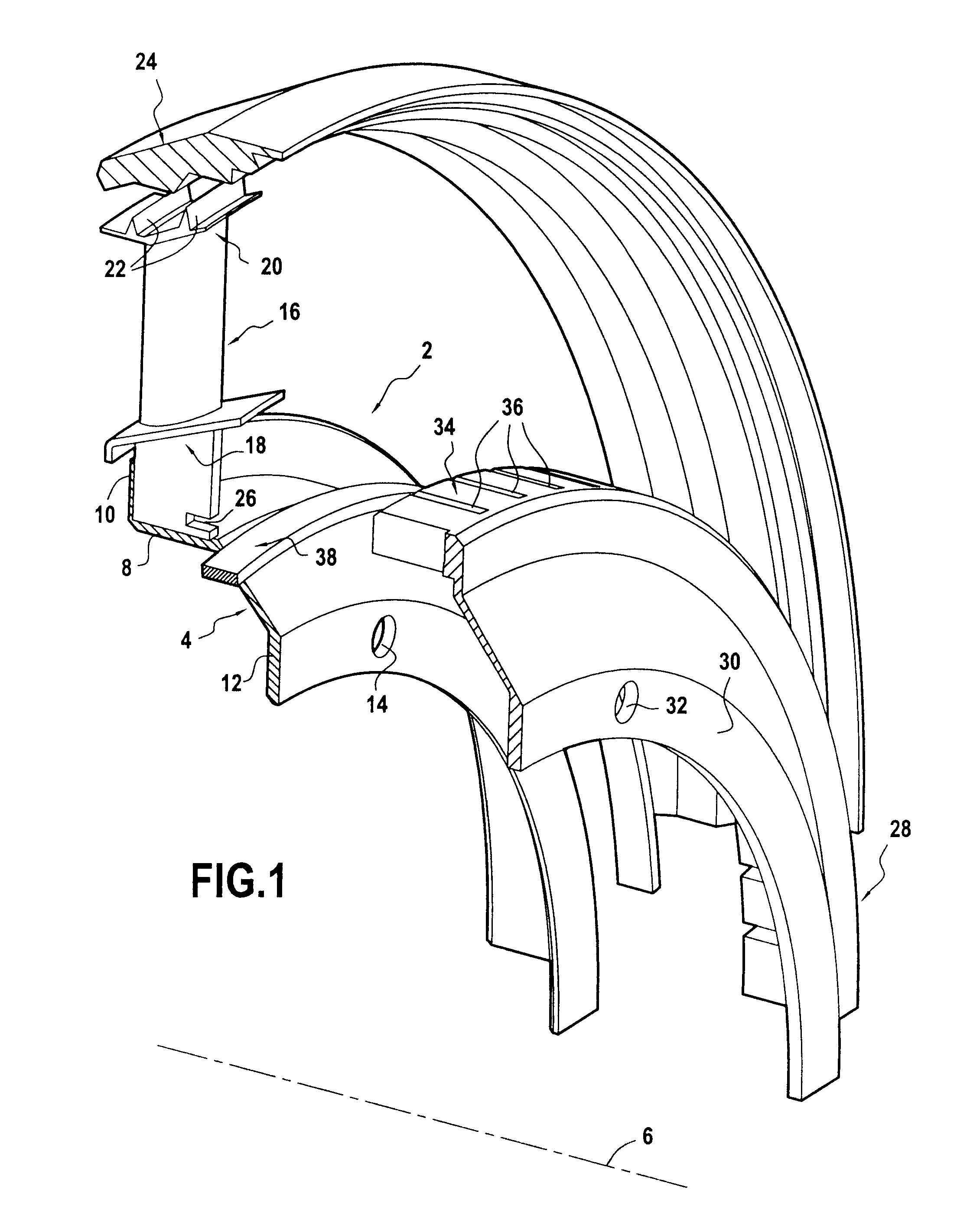
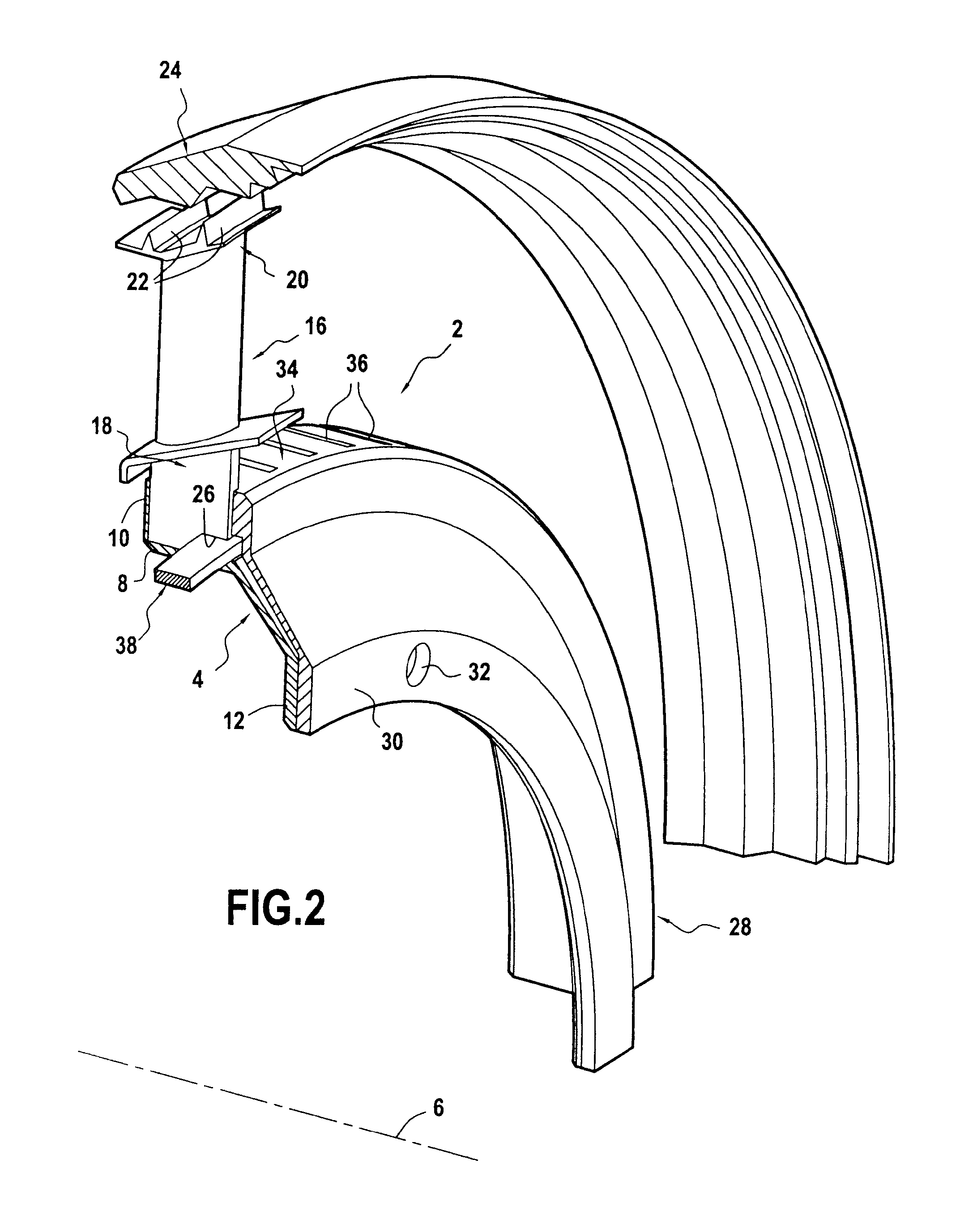
[0020]The invention is applicable to various types of turbomachine rotor wheels fitted with blades made of a composite material, and in particular the compressor and turbine rotor wheels of various gas turbine spools, e.g. a low pressure turbine rotor wheel of an aviation turbomachine, such as that shown in FIGS. 1 to 4.

[0021]In the description below, the terms “upstream” and “downstream” are used relative to the flow direction of the gas stream passing through the low pressure turbine.

[0022]The rotor wheel 2 shown in FIGS. 1 to 4 comprises in particular an annular metal mounting plate 4 that is centered on the axis of rotation 6 of the wheel. The mounting plate 4 includes in particular an axial wall 8 that is extended firstly upstream by an outwardly-directed radial upstream wall 10 (i.e. going away from the axis of rotation 6), and secondly downstream by a radial downstream wall 12 provided with holes 14.

[0023]The rotor wheel 2 also includes a plurality of blades 16 made of compos...


PUM


Abstract

A turbomachine rotor wheel including blades made of composite material; an annular mounting plate; a plurality of composite material blades mounted on the mounting plate, each blade also including a top platform at its tip carrying radial labyrinth teeth; an orientation disk fastened coaxially around the mounting plate and including at its outer periphery a plurality of axial slots that are open at one end, each slot presenting a cross-section that matches the cross-section of a blade root so as to hold it angularly in position by co-operation of shapes; and a variable-diameter spring ring housed in part in an axial notch formed in each blade root and projecting axially relative thereto, the spring ring to come into radial abutment against an inside surface of the orientation disk during radial outward movement of the blades relative to the mounting plate.

Description

BACKGROUND OF THE INVENTION[0001]The present invention relates to the general field of turbomachine blades made of composite material comprising fiber reinforcement densified by a matrix.[0002]The intended field is that of rotor wheels having composite material blades for use in aeroengines or in industrial turbines.[0003]Proposals have already been made to fabricate turbomachine blades out of composite material. For example, reference may be made to the French patent application FR 08 / 58090 (not yet published) filed jointly in the names of Snecma and Snecma Propulsion Solide that describes fabricating a turbomachine blade by making a fiber preform by three-dimensional weaving and by densifying the preform with a matrix.[0004]When a rotor wheel has blades that are made of metal, the wheel generally has a plurality of metal blades mounted via their roots on a metal disk, and a metal casing is placed around the rotor wheel.[0005]During assembly (when cold) of the rotor wheel inside th...

Claims


Application Information

Patent Timeline
IPC IPC(8): F01D11/02F01D11/12
CPCF01D5/282F01D5/303Y02T50/672F01D11/18F01D5/32F01D5/3069Y02T50/60
Inventor BLANCHARD, STEPHANEGENDRAUD, ALAIN
Owner SN DETUDE & DE CONSTR DE MOTEURS DAVIATION S N E C M A
Why Eureka
Try Eureka