Communication apparatus and communication method
a communication apparatus and communication method technology, applied in the direction of power management, climate sustainability, sustainable buildings, etc., can solve the problems of increasing transmission power, communication medium may be broken, transmission power reduction, etc., to reduce transmission power of transmission amplifiers, transmission, and maximum communication distance.
- Summary
- Abstract
- Description
- Claims
- Application Information
AI Technical Summary
Benefits of technology
Problems solved by technology
Method used
Image
Examples
first embodiment
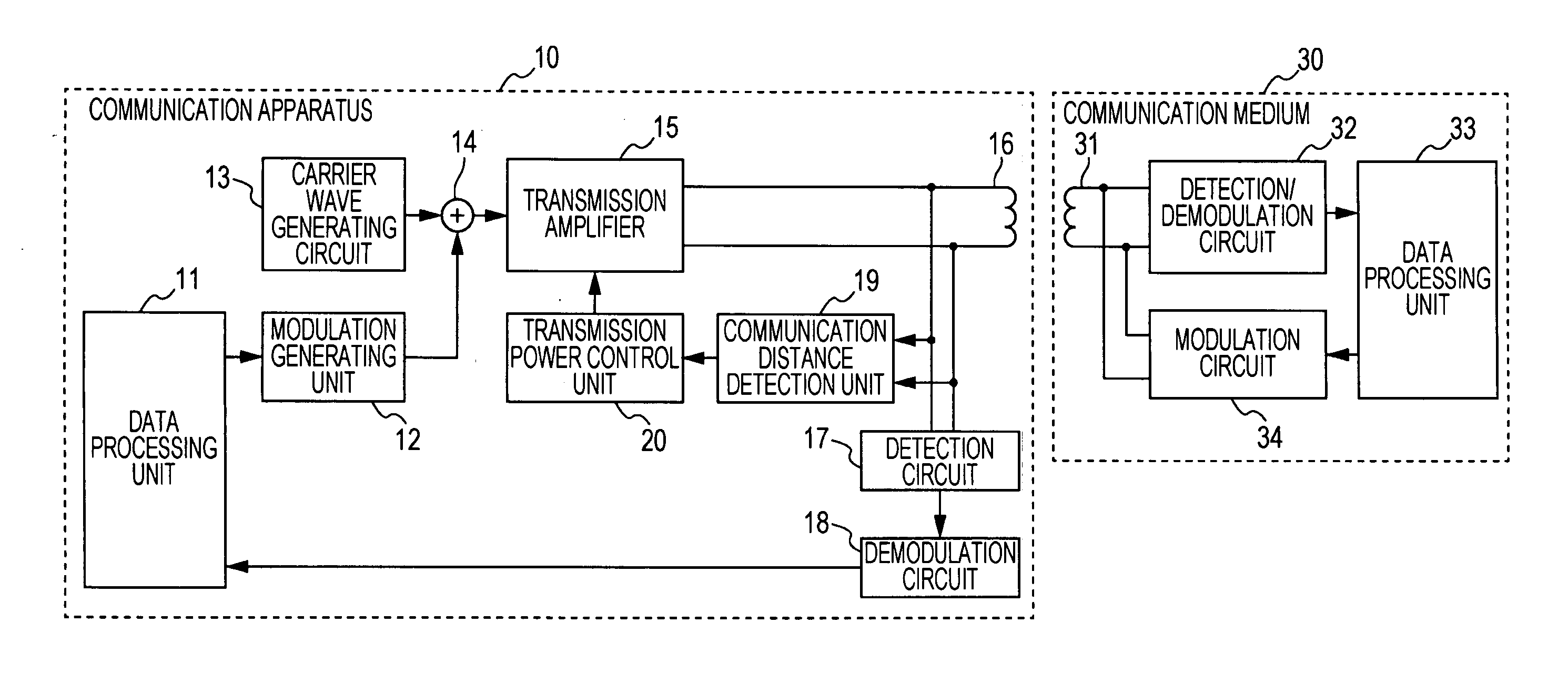
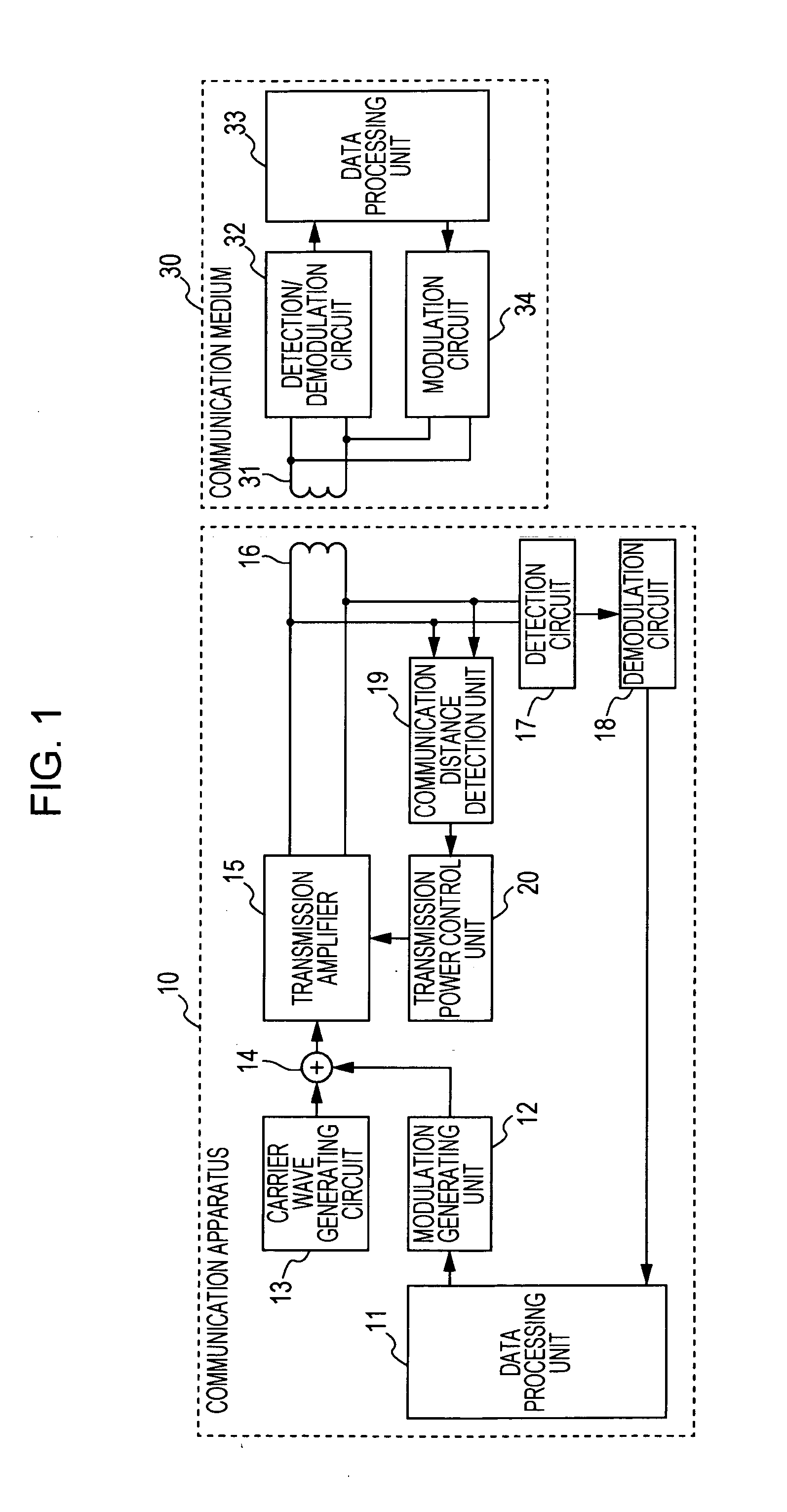
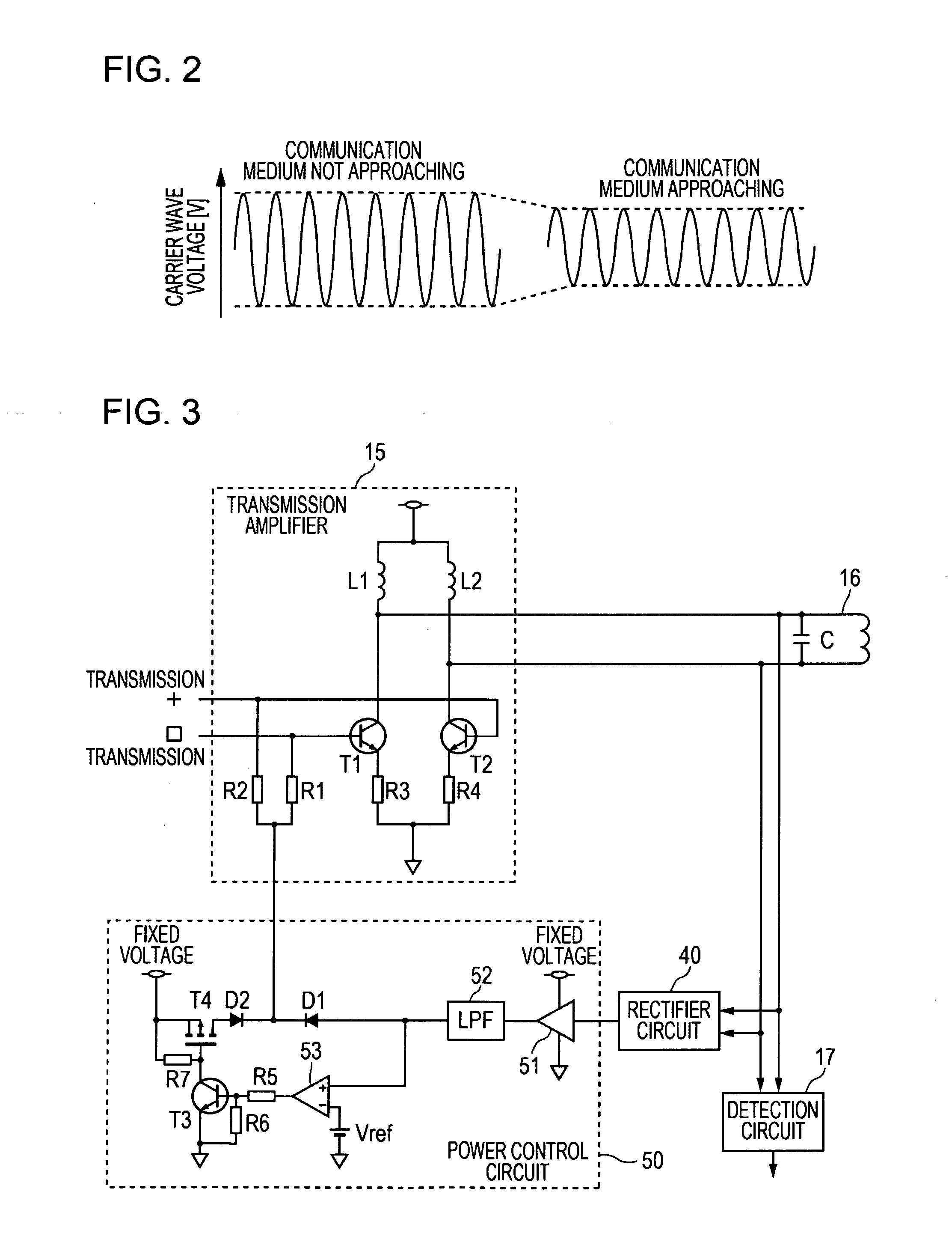
[0038]In the communication apparatus 10 control of the transmission power of the transmission amplifier 15 is realized by controlling the base bias voltage of transistors included in the transmission amplifier 15.
[0039]The transmission amplifier 15 has two transistors T1 and T2 that form a differential amplification circuit having a certain frequency. To the bases of the transistors T1 and T2, resistors R1 and R2 that receive the base bias voltage are connected, and the emitters of the transistors T1 and T2 are connected to the ground through resistors R3 and R4. The collectors of the transistors T1 and T2 are connected to a power source through inductors L1 and L2 and also connected to the antenna 16. To the antenna 16, a capacitor C included in a parallel resonant circuit is connected.
[0040]Terminals at both ends of the antenna 16 are connected to a rectifier circuit 40, which corresponds to the communication distance detection unit 19 of FIG. 1. The rectifier circuit 40 attenuat...
second embodiment
[0048]The communication apparatus 10 is configured to secure minimum power when the transmission power of the transmission amplifier 15 is controlled such that the transmission power decreases as the communication medium 30 approaches the communication apparatus 10, so that the transmission power of the transmission amplifier 15 does not decrease too much and does not cause a power shortage.
[0049]Therefore, the communication apparatus 10 according to the second embodiment has a minimum power securing circuit in the power control circuit 50. The minimum power securing circuit 54 has a voltage divider that includes two resistors R8 and R9 connected in series, and a diode D3 connected to a node between the resistors R8 and R9. The diode D1 that supplies a variable monitoring voltage, the diode D2 that supplies a fixed high voltage, and the diode D3 that supplies a fixed low voltage for securing minimum power together form an OR circuit. The voltage of whichever diode has the highest v...
third embodiment
[0051]FIG. 9 is a schematic circuit diagram illustrating an example of the configuration of a communication apparatus according to a In FIG. 9, the same components as those illustrated in FIGS. 3 and 7 are given the same reference numerals so as to omit detailed description thereof.
[0052]The communication apparatus 10 according to the third embodiment performs control of the transmission power of the transmission amplifier 15 by attenuating the level of a signal input to the transmission amplifier 15, that is, the amplitude of a modulated or an unmodulated carrier wave.
[0053]In this embodiment, the attenuation of a signal input to the transmission amplifier 15 is performed by reducing the power supply voltage of an input circuit that receives the signal. That is, the power control circuit 50 has a voltage regulator 55 that receives the monitoring voltage output from the low-pass filter 52 and that adjusts the power supply voltage to a variable output voltage, and the transmission a...
PUM
 Abstract
Description
Claims
Application Information
 - R&D
- Intellectual Property
- Life Sciences
- Materials
- Tech Scout
- Unparalleled Data Quality
- Higher Quality Content
- 60% Fewer Hallucinations
Browse by: Latest US Patents, China's latest patents, Technical Efficacy Thesaurus, Application Domain, Technology Topic, Popular Technical Reports.
© 2025 PatSnap. All rights reserved.Legal|Privacy policy|Modern Slavery Act Transparency Statement|Sitemap|About US| Contact US: help@patsnap.com


