System and method for evaluating application suitability in execution environment
a technology of application suitability and execution environment, applied in the field of computer-based evaluation, can solve the problems of increasing the cost of managing client resources
- Summary
- Abstract
- Description
- Claims
- Application Information
AI Technical Summary
Benefits of technology
Problems solved by technology
Method used
Image
Examples
embodiment 1
[0060]A first embodiment of the present invention will be explained.
[0061]The first embodiment relates to a network system in which a physical environment and a streaming-type virtual environment coexist. This network system is based on technology, which isolates an access by an application to a specific information resource that comprises setting information (for example, a registry) and an execution library (for example, a DLL (Dynamic Link Library). This network system comprises an application server, and this application server delivers a virtual application, which will be described hereinbelow, to a client.
[Overall Configuration]
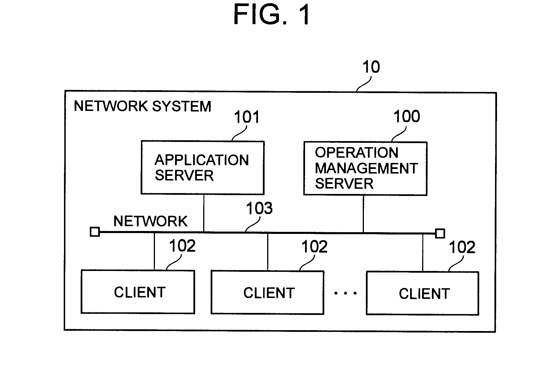
[0062]FIG. 1 is a diagram showing the overall configuration of this embodiment.
[0063]A network system 10 comprises a management server 100, an application server 101, and one or more clients 102, and these components are coupled to a network 103.
[0064]The network 103 is a communication network for communicably coupling together the management server 100...
first embodiment
Overview of First Embodiment
[0119]FIG. 5 is a diagram showing an overview of this embodiment. Furthermore, in FIG. 5, the virtual application is abbreviated as “VAP” and the physical application is abbreviated as “PAP”.
[0120]First of all, the administrator registers information related to an application from an application information registration screen 2400, which will be explained using FIG. 24. The management server 100 updates the characteristics table 211 based on the registered information (Step s1).
[0121]Next, the management server 100 collects the information stored in the inventory table 418 and the information stored in the utilization log table 419 from all the clients of the network system 10, and updates the usage table 212 on the basis of this collected information (Step s2).
[0122]Next, the management server 100 evaluates the characteristics of the application in the respective execution environments based on the characteristics table 211 and the usage table 212, and ...
embodiment 2
[0271]Next, a second embodiment of the present invention will be explained. In so doing, only the points of difference with the first embodiment will be explained, and explanations of the points in common with the first embodiment will either be omitted or abbreviated (this also holds true for the third through the sixth embodiments below).
[0272]The second embodiment is related to a network system in which a host-type virtual environment exists. The client remotely executes an application in the application server.
[0273]FIG. 25 is a diagram showing the configuration of an application server 2501 in this embodiment.
[0274]The application server 2501 of the second embodiment differs from that of the first embodiment in that the application is not delivered to the client 102, but rather the application is executed on the OS of the application server 101 and the screen information is sent to and received from the client 102. Therefore, the configuration of the program and data stored in ...
PUM
 Abstract
Description
Claims
Application Information
 - R&D
- Intellectual Property
- Life Sciences
- Materials
- Tech Scout
- Unparalleled Data Quality
- Higher Quality Content
- 60% Fewer Hallucinations
Browse by: Latest US Patents, China's latest patents, Technical Efficacy Thesaurus, Application Domain, Technology Topic, Popular Technical Reports.
© 2025 PatSnap. All rights reserved.Legal|Privacy policy|Modern Slavery Act Transparency Statement|Sitemap|About US| Contact US: help@patsnap.com


