Hose clamp with parallel tightening and rapid release

Inactive Publication Date: 2011-11-10
POSNER SAMUEL LEWIS
View PDF6 Cites 20 Cited by
  • Summary
  • Abstract
  • Description
  • Claims
  • Application Information

AI Technical Summary

Problems solved by technology

None of which have completely satisfied the use advantages but have unfortunately incorporated many disadvantages in there overall design.
Some of the problems have been addressed but not adequately and never completely in one clamp.
A frequent problem is hose clamps and hoses are positioned in confined spaces or visually out of sight so that only one hand may be used when, tightening or loosening a clamp.
Unfortunately tight areas and hard to reach places are common when using hoses and fittings.
Kreft has positioned a tightening wrench opposed to the axial of the hose, however it appears that the hexagonal wrench can only be inserted on one side of the head limiting its practical use in hard to reach spaces.
Also, the patent does not describe in detail the means of attachment of the locking and gear section to the band or strap, which is critical to its function and cost of manufacture.
The strength of the teeth is also a factor due to their nominal width as well as the depth of engagement in the slots in the strap are also questionable.
Difficulty appears when the engaging member tab, holding the gear in a stop position where as the hexagonal wrench must be withdrawn so the gear will slide into position by means of a spring.
If the hexagonal wrench is removed, force cannot be maintained against the spring causing counter rotation of the gear releasing the strap.
Small thin metal tabs are all that prevents the clamp from disengaging as well as a fine steel spring to engage the stop incidence of corrosion are common and will certainly cause this clamp to fail.
All of which have exposed mechanisms that can become entangled with adjacent apparatus or cause injury by having exposed sharp edges.
It also appears some difficulty would be encountered releasing the ratchets when under reverse force from the tightened strap.
Kitts U.S. Pat. No. 2,383,199 (1945) as mentioned above this device may also be accidentally released by the exposed position of the ratchet paw.
Another major flaw in all the above clamps is that the parts are all various types of metal costly to fabricate, manufacture and assemble.
In a relatively short time, under certain conditions, all metal even high quality will corrode, fatigue and erode, especially made from thin sheet metal with no substantial thickness.
It has been demonstrated that “worm gear” design when over tightened will fracture or bend the metal between each perforation of the strap since they are close together with little metal support between each perforation.
Little surface contact between the “worm gear” and the perforations also causes failure.
Although it appears that in order to release the gear from the slotted strap it would have to be pried up with a tool not easily accomplished in tight surroundings or areas out of sight.
In addition all the clamps cited above are fabricated from metal, costly to fabricate, manufacture and assemble.
Although it has no means to disengage and is designed to be finger tightened only limiting its use.
All hose clamps of this type as described above in various forms suffer from a number of disadvantages:(a) Hose clamps based on the “worm gear” design principle cannot be applied or removed using only one hand.
A distinct disadvantage in many applications.(b) All prior art hose clamps designed for medium pressure applications are fabricated from metal.
Under certain adverse conditions such as exposure to acids, salts, electrolysis, flexing, vibrations and the like may degrade these clamps to the point of failure, even high quality stainless steel.(c) The majority of hose clamps used today do not embody means to rapidly and easily disengage.(d) The need to use tools to install or remove hose clamps such as slotted screwdrivers or ratchets in places inaccessible or completely out of view is cumbersome a distinct disadvantage.(e) Another disadvantage is the inability to color code in order to identify the contents being carried within a hose and could be a safety issue.(f) To assembly metal hose clamps you must consider the cost of material, overall energy necessary to manufacture and form parts, labor and assembly equipment, manufacturing space, shipping, as well as other peripheral expenses.
These costs are exceedingly greater than a polymeric composite, injection molded, hose clamp.(g) Some hazards of using metal hose clamps are injuries and cuts from sharp edges and accidental electrical conductivity.

Method used


Image

  • Hose clamp with parallel tightening and rapid release
  • Hose clamp with parallel tightening and rapid release
  • Hose clamp with parallel tightening and rapid release

Examples


Embodiment Construction

FIGS. 1 through 5—Preferred Embodiment

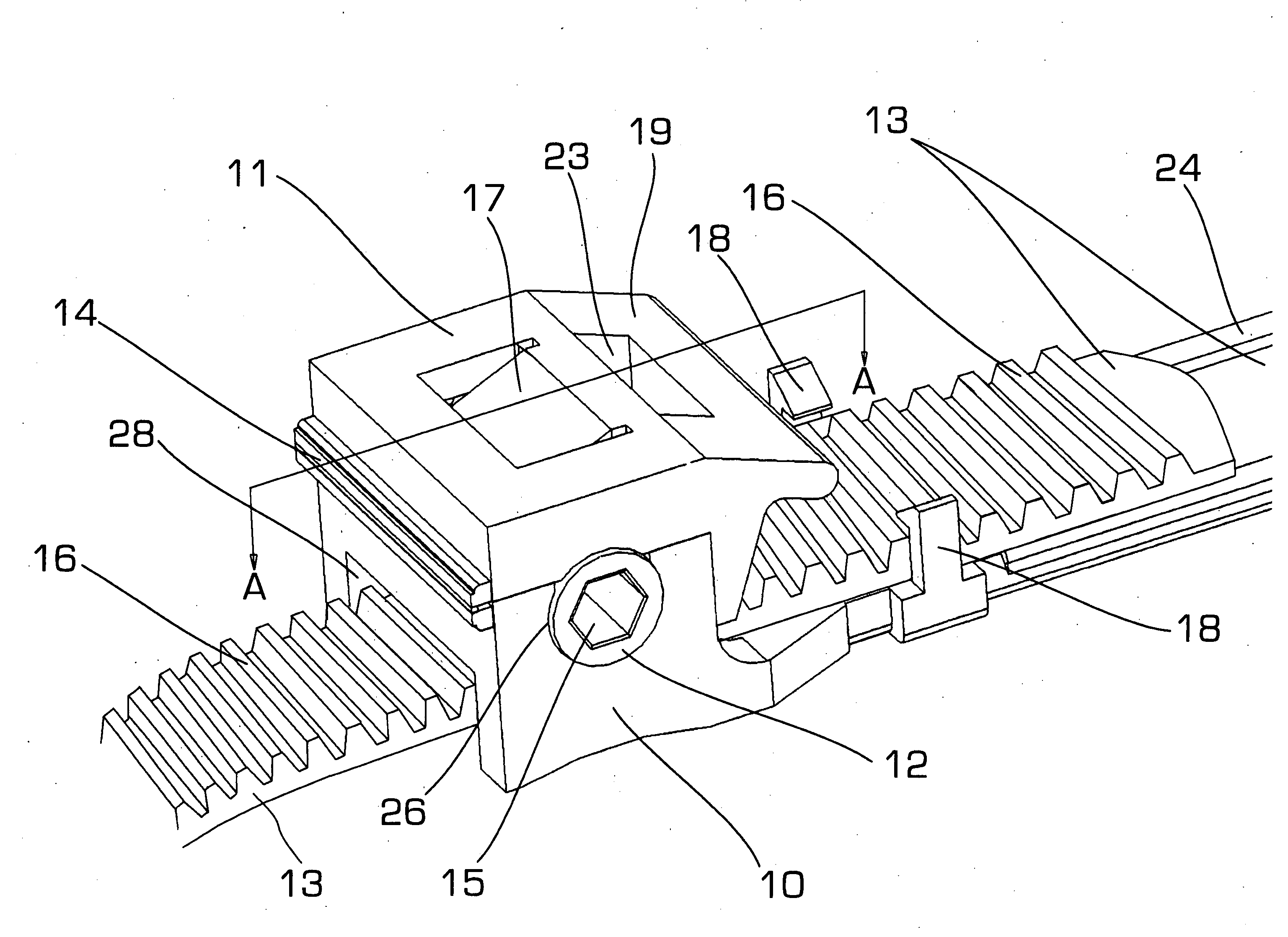
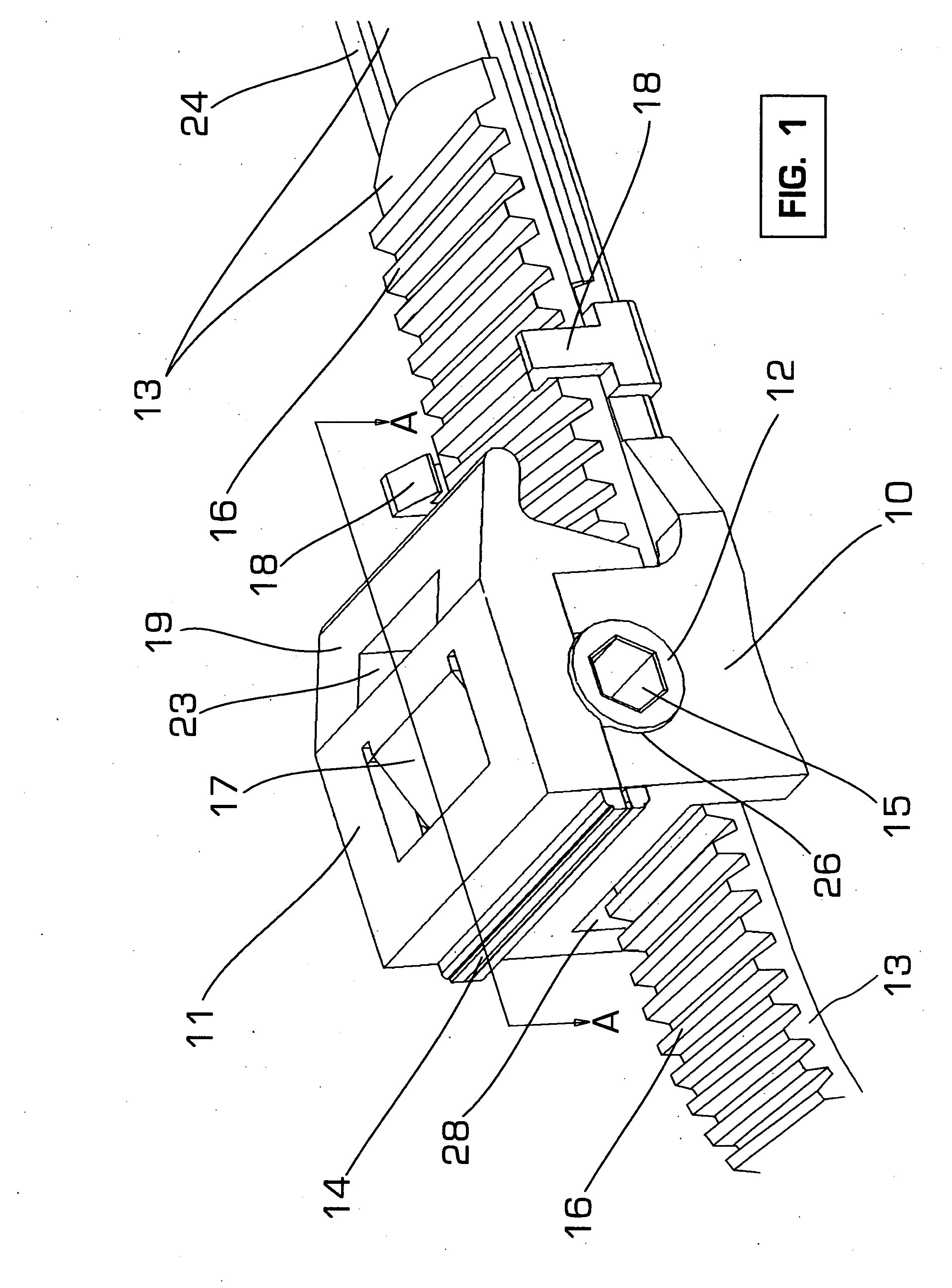
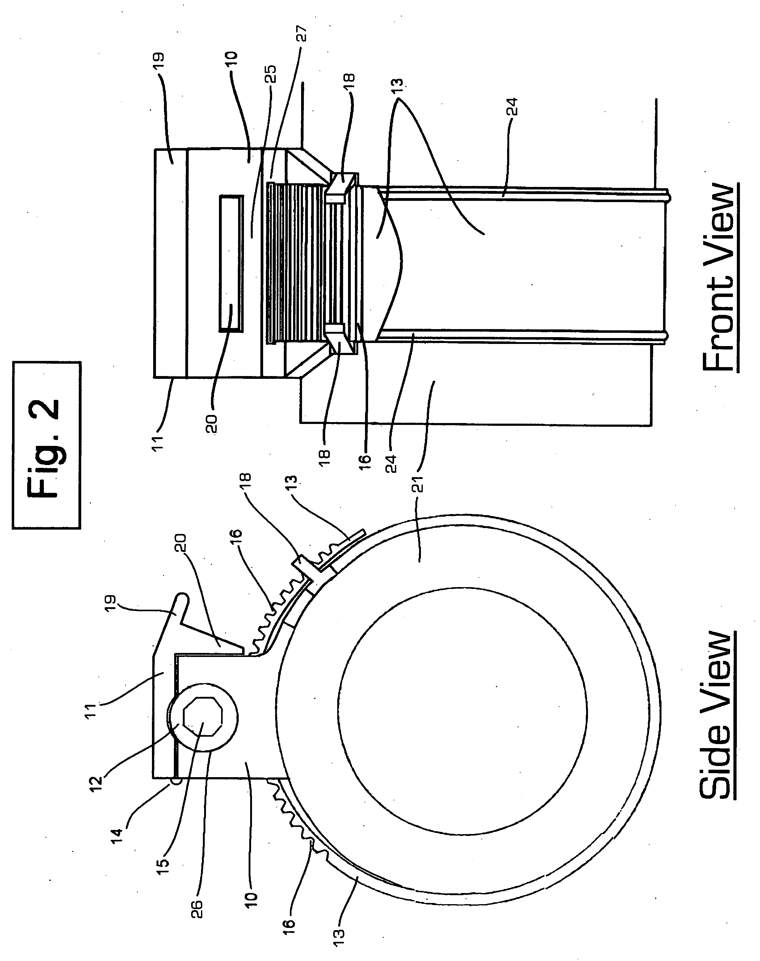
[0061]The preferred embodiment of the hose clamp with parallel tightening and rapid release as illustrated in FIGS. 1 through 5 comprising the molded support base 10 including the molded support base top 11 which is attached to the molded support base 10 by a molded hinge 14 and a rapid release hold down top lock 20 as illustrated in FIGS. 2,3,4 and 5 a flexible paw 17 or an eccentric wedging member is molded in the top of the molded support base 11, the rapid release finger grip 19 the rapid release hold down top lock 20 the lock bar 25 shown in FIGS. 2,3,4 and 5 and two band strap retainers 18 shown in FIGS. 1,2,3,4 and 5 which hold the flexible grooved band strap 13 also shown are the grooves 16 molded in the flexible grooved band strap 13, which enters the molded support base 11 by a band strap entrance port 28 and a band strap exit port 27 as shown in FIGS. 1,2,3, and 4 a grooved molded rotating cylinder 12 is held within the molded support...


PUM


Abstract

An improved clamp constricting objects to be held in place including hoses wires tubes. One embodiment having some or all plastic molded parts one of which is a support base (10) to one side is attached a partially grooved or fully flexible grooved band strap (13) where as the other end is free to enter a band strap entrance port (26) thereby contact is made with a matching grooved rotating cylinder (12) held by two bearings. The band strap (13) advances encircling objects to be held. The support base top (11) is closed and locked by the rapid release hold down top lock (20) confining the grooved molded rotating cylinder (12) engaging a flexible paw (17) allowing advancing rotation only, preventing the grooved molded band strap (13) from retracting. Six sided wrench or tool is inserted into the cylinder cavity (15) forcefully rotating the grooved rotating cylinder (12) advancing the flexible grooved band strap (13) through exit port (27) being held down by band strap retainers (18). A rapid release finger grip (19) releases a rapid release hold down top lock (20) lifting the molded support base top (11) disengaging the flexible paw (17) from the grooved molded rotating cylinder (12) allowing counter rotation of the grooved molded rotating cylinder (12) retracting the flexible grooved band strap (13) freeing the constricted objects.

Description

CROSS-REFERENCE TO RELATED APPLICATIONS[0001]This application claims the benefit of provisional patent application Ser. No. 61 / 336,336 filed 2010 Jan. 21 by the present inventor.FEDERALLY SPONSORED RESEARCH[0002]Not ApplicableSEQUENCE LISTING OR PROGRAM[0003]Not ApplicableBACKGROUND[0004]1. Field of Invention[0005]This invention relates to clamps particularly hose clamps that are used to constrict hoses on fittings or other objects to be confined.[0006]2. Prior Art[0007]It is common practice to fasten a tube or hose to an end fitting or connector so the contents of the tube or hose may reach its destination or the final connection. The hose or tube must be securely attached to the fitting usually this is accomplished by compressing the tube or hose around the circumference of the fitting. These devices are known generally as hose clamps.[0008]The present invention relates generally to hose clamping devices and particularly an improved hose clamp apparatus. Other general uses of this...

Claims


Application Information

Patent Timeline
Patent Type & Authority Applications(United States)
IPC IPC(8): B65D63/00
CPCF16L33/035Y10T24/1498Y10T24/1482Y10T24/1406Y10T24/1424Y10T24/142Y10T24/14Y10T24/1422
Inventor POSNER, SAMUEL LEWIS
Owner POSNER SAMUEL LEWIS
Why Eureka
Try Eureka